Unstacking method for brake discs through robot 3D visualization

A brake disc and robot technology, applied in the field of robots, can solve the problems of poor material rack manufacturing accuracy, brake disk pickup, and low material rack manufacturing accuracy, and achieve the effect of saving space and improving flexibility

Active Publication Date: 2017-03-15
SHANGHAI FANUC ROBOTICS
View PDF6 Cites 5 Cited by
  • Summary
  • Abstract
  • Description
  • Claims
  • Application Information

AI Technical Summary

Problems solved by technology

Due to the low manufacturing precision of the material rack itself, and the storage of the brake discs in the material frame also has precision errors, the position of the brake discs in the space is not good, so most manufacturers cannot realize automation in the head-of-line unit of the automatic brake disc production line. Rely on manual placement of brake discs on conveyor belts or positioning fixtures
The current problem is that the manufacturing accuracy of the material frame is poor, which leads to the deviation of the three-dimensional position of the brake disc, while the traditional robot can only pick up the workpiece from a fixed and precise position, and cannot be used to pick up the brake disc from the material frame.

Method used


Image

  • Unstacking method for brake discs through robot 3D visualization
  • Unstacking method for brake discs through robot 3D visualization
  • Unstacking method for brake discs through robot 3D visualization

Examples


Embodiment approach

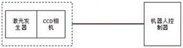
[0042] In further embodiments of the present invention, please continue to refer to figure 1 As shown, a 3D camera kit 2 is shown, and the 3D camera kit 2 includes a CCD camera and a laser generator.

[0043] In a further embodiment of the present invention, the laser emitter emits two laser beams, and the position of the brake disc in the vertical direction is detected by the two laser beams.

[0044] In a further embodiment of the present invention, the CCD camera can be used alone as a 2D vision system, and the position of the brake disc on the horizontal plane is detected by the CCD camera.

[0045] In a further embodiment of the present invention, the 3D camera kit 2 is electrically connected to the controller of the robot, and the 3D camera kit is arranged at the end of the gripper 3 .


PUM


Abstract

The invention discloses an unstacking method for brake discs through robot 3D visualization. The method comprises the steps that an operator awaits a material frame to fall to an approximate charging position; a robot detects the two opposite corners of the material frame through a 3D camera kit, and then the approximate position of the material frame is determined; the position of the 3D camera kit is adjusted through the robot, and the 3D camera kit is made to be located over the material frame; the 3D camera kit is used for detecting the position of one brake disc in the material frame through a 3D brake disc visual identity technology, and the robot is guided to pick the brake disc up; and the robot moves the brake disc to a discharging conveying line or a clamp through a gripper. Through the method, after the material frame loading with the brake discs directly falls to the approximate charging position, the robot can achieve accurate pickup, and the brake discs do not need to be accurately positioned any more.

Description

technical field [0001] The invention relates to the technical field of robots, in particular to a method for realizing brake disc dismantling by using robot 3D vision. Background technique [0002] At present, before the brake disc enters the production line for processing, it is generally used to put the brake disc into the material rack. Due to the low manufacturing precision of the material rack itself, and the storage of the brake discs in the material frame also has precision errors, the position of the brake discs in the space is not good, so most manufacturers cannot realize automation in the head-of-line unit of the automatic brake disc production line. Rely on manual placement of brake discs into conveyor belts or positioning jigs. The current problem is that the manufacturing accuracy of the material rack is poor, which leads to the deviation of the three-dimensional position of the brake disc. The traditional robot can only pick up the workpiece from a fixed and ...

Claims


Application Information

Patent Timeline
Patent Type & Authority Applications(China)
IPC IPC(8): B25J9/16B65G61/00
CPCB25J9/1697B65G61/00
Inventor 杨恒亮李广伟童梁吴建文李海权
Owner SHANGHAI FANUC ROBOTICS
Why Eureka
Try Eureka