Magnetic clutch mechanism and clutch device

A clutch mechanism and clutch device technology, applied in magnetic drive clutches, clutches, non-mechanical drive clutches, etc., can solve the problems of difficult climbing, walking, slippage, etc.

Active Publication Date: 2018-09-07
融创达科技成果转化(江苏)有限公司
View PDF5 Cites 0 Cited by
  • Summary
  • Abstract
  • Description
  • Claims
  • Application Information

AI Technical Summary

Problems solved by technology

[0002] At present, electric toy cars for children are mostly used. Electric drive drives the wheels to rotate through the drive motor, so that the toy car can move forward. Insufficient and difficult to climb; secondly, because the two rear wheels are driven by two separate motors with the same speed, once the inner and outer wheels rotate at the same speed, it will cause slipping or even rollover, which is dangerous

Method used


Image

  • Magnetic clutch mechanism and clutch device
  • Magnetic clutch mechanism and clutch device
  • Magnetic clutch mechanism and clutch device

Examples


Embodiment Construction

[0029] The present invention will be further described below in conjunction with the accompanying drawings.

[0030] Such as Figures 10 to 11 The dual-power drive stroller shown in the figure includes a wheel 7, an electric driver 2, and a pedal shaft 1. An inner clutch device and an outer clutch device are provided on both sides of the wheel 7, and the pedal shaft 1 is pierced and pivotally connected. Inside and outside clutch device and wheel 7, this inside and outside clutch device is a kind of clutch device of magnetic conduction, and inside and outside clutch device is two identical clutch devices in essence, just because the difference of driving device causes concrete structure to be slightly different.

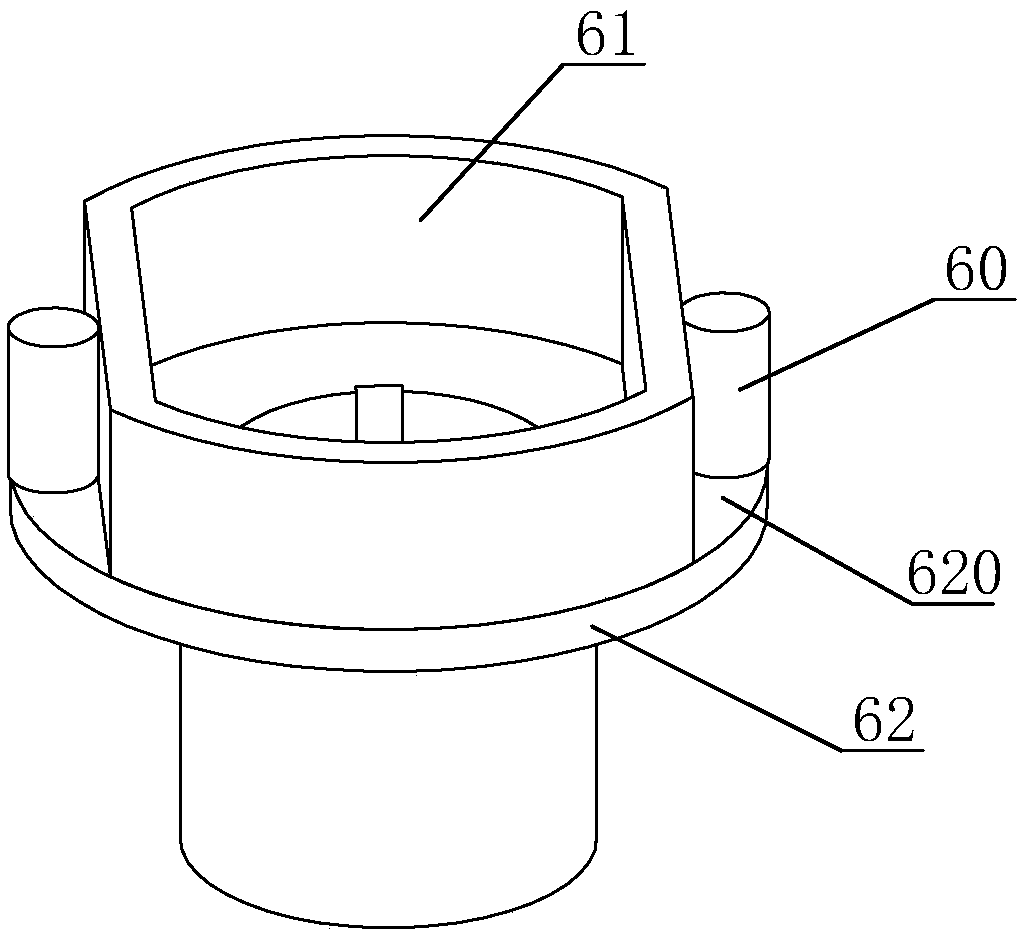
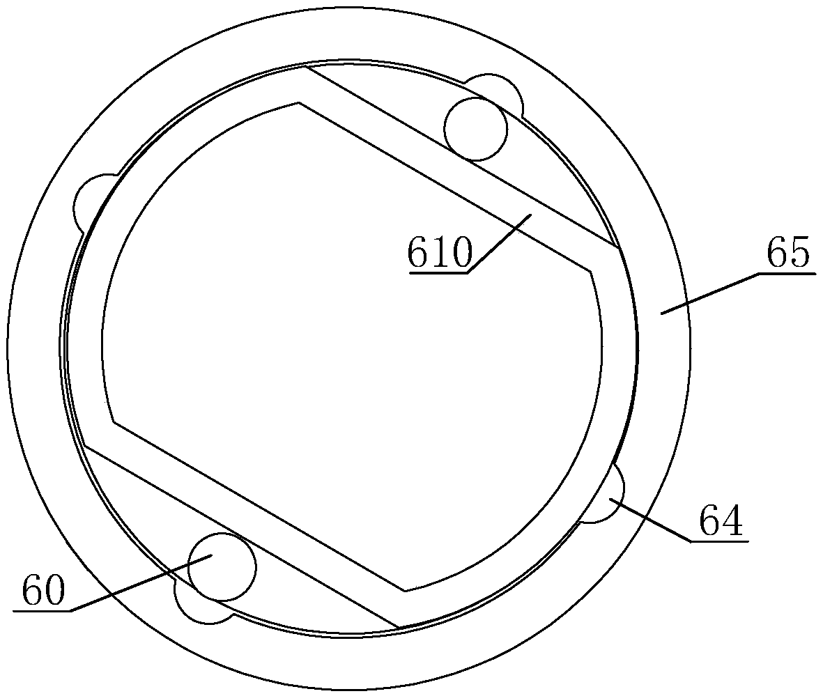
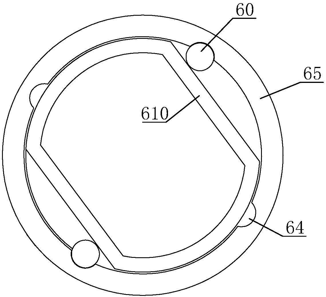
[0031] Such as Figure 4 As shown, the inner clutch device includes a linkage frame 30 as a driving element, a linkage unit 6, a fixed frame 70 as a driven element, and a fixed seat 31. The linked frame 30 is fixed on the output end of the driver 2, and the fixed fra...


PUM


Abstract

The invention discloses a magnetic conduction engaging and disengaging mechanism and engaging and disengaging device. The engaging and disengaging device comprises the engaging and disengaging mechanism, a driving part and a driven part. The engaging and disengaging mechanism comprises magnetic rods, a guide sleeve and a guide ring. The guide sleeve is provided with a guide plate. The guide ring is provided with at least one flat edge. The magnetic rods are attached to the flat edges. A rotating groove is formed in the driven part. The rotating groove, the guide ring and the guide plate are the same in diameter. Limiting grooves are further formed in the rotating groove. When the engaging and disengaging device is applied to child vehicle wheels, the driven part and the driving part on the engaging and disengaging device can be in linkage through instant accelerating, when a relative difference happens to the rotating speed of the driving part and the rotating speed of the driven part, the driving part and the driven part can be separated, and the engaging and disengaging manner is flexible. By means of the additionally-arranged engaging and disengaging device, multiple kinds of drive force can be adopted in a child vehicle, both electric drive and manual drive can be adopted, and the problems of turning slipping, insufficient climbing power and the like can be solved.

Description

technical field [0001] The invention relates to a connection structure of a stroller wheel, in particular to a magnetic conduction clutch mechanism and a clutch device. Background technique [0002] At present, electric toy cars for children are mostly used. Electric drive drives the wheels to rotate through the drive motor, so that the toy car can move forward. Insufficient and difficult to climb; secondly, because the two rear wheels are driven by two separate motors with the same speed, once the inner and outer wheels rotate at the same speed, it will cause slipping or even rollover, which is dangerous. There is also a pedal type kart, the power source is human pedaling, and its structure is similar to a tricycle. [0003] Therefore, the two drives each have their own advantages, but how to combine the two is still a problem in the toy electric vehicle industry. Contents of the invention [0004] The purpose of the present invention is to provide a magnetic conduction...

Claims


Application Information

Patent Timeline
Patent Type & Authority Patents(China)
IPC IPC(8): F16D27/01
CPCF16D27/01
Inventor 张彬其
Owner 融创达科技成果转化(江苏)有限公司
Why Eureka
Try Eureka