
Air conditioning equipment, draught fan system and draught fan system control method

A technology of fan system and control method, applied in fan system and fan system control, air-conditioning equipment field, can solve the problems that the machine cannot run stably for a long time, the high and low pressure compression ratio cannot be too large, etc., to improve quality stability and expand temperature Scope, the effect of expanding the scope of use

Inactive Publication Date: 2017-03-15
GUANGDONG CHIGO HEATING & VENTILATION EQUIP CO LTD
View PDF7 Cites 11 Cited by
  • Summary
  • Abstract
  • Description
  • Claims
  • Application Information

AI Technical Summary

Problems solved by technology

However, due to the special needs of some customers, such as cooling when the ambient temperature is lower than 0°C in winter, and heating when the ambient temperature is 30°C in summer, the operating range of the air conditioner compressor itself and the compression ratio of high and low pressure cannot be exceeded. The big problem is that the machine cannot run stably for a long time only by using the above scheme

Method used


Image

  • Air conditioning equipment, draught fan system and draught fan system control method
  • Air conditioning equipment, draught fan system and draught fan system control method
  • Air conditioning equipment, draught fan system and draught fan system control method

Examples


Embodiment Construction

[0031] The following will clearly and completely describe the technical solutions in the embodiments of the present invention with reference to the accompanying drawings in the embodiments of the present invention. Obviously, the described embodiments are only some, not all, embodiments of the present invention. Based on the embodiments of the present invention, all other embodiments obtained by persons of ordinary skill in the art without making creative efforts belong to the protection scope of the present invention.

[0032] The core of the present invention is to provide a fan system and a fan system control method, which can make the fan system have a wider application range. Another core of the present invention is to provide an air conditioner including the above fan system.

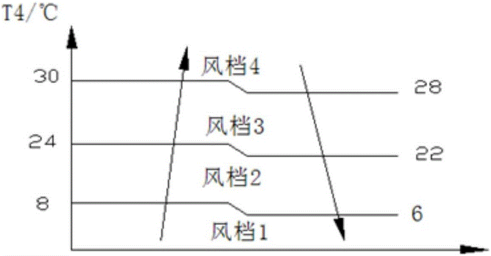
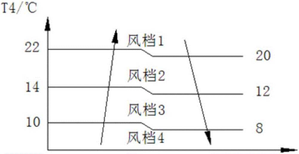
[0033] Please refer to Figure 1 to Figure 4 , figure 1 A flow chart of the fan system control method provided by the present invention; figure 2 The temperature-wind shift diagram of the cool...


PUM


Abstract

The invention discloses a draught fan system control method. The draught fan system control method is applied to a draught fan system which comprises two or more draught fans. The two or more draught fans form four or more wind grades different in wind speed. The draught fan system control method comprises the steps of obtaining the outdoor environment temperature, and detecting the current use mode; when the current use mode is a refrigeration mode, keeping wind speed of the selected wind grade being positively correlated with the outdoor environment temperature; and when the current use mode is a heating mode, keeping wind speed of the selected wind grade being negatively correlated with the outdoor environment temperature. By means of the draught fan system control method, increase of the wind grades and multiple types of selection and variation of wind speed are achieved; the used temperature range is widened; a machine can conduct refrigeration and heating within a large environment temperature range; in addition, stable operation of the system can be maintained; the system is safe and high in reliability; the application scope is widened; and meanwhile, quality stability of products is further improved. The invention further discloses the draught fan system for implementing the draught fan system control method and air conditioning equipment provided with the draught fan system.

Description

technical field [0001] The invention relates to the technical field of chiller control, and more specifically, to a fan system and a method for controlling the fan system. In addition, the present invention also relates to an air conditioner comprising the above fan system. Background technique [0002] At present, in commonly used air conditioners, the AC fan used is mostly one-speed wind or two-speed wind. When using a single-speed fan, it can basically meet the requirements for cooling in summer and heating in winter. Using a two-speed fan can widen the operating environment temperature range of the machine, and the adjustment performance under different working conditions is better. The general operating environment temperature range is 21 Cooling within the ambient temperature range of ℃ to 43°C, and heating within the ambient temperature range of -10°C to 20°C. In the prior art, some machines with better configuration can be used in a relatively wider range. However...

Claims


Application Information

Patent Timeline
IPC IPC(8): F24F11/00F24F11/04
CPCF24F11/30F24F11/74F24F11/77F24F2110/10F24F2110/12Y02B30/70
Inventor 黎志瑜黄振韶李球刘华栋高德福
Owner GUANGDONG CHIGO HEATING & VENTILATION EQUIP CO LTD
Learn More