Image Sensor Mounting Error Separation Method Based on Vision Measurement

An image sensor and visual measurement technology, which is applied in the direction of measuring devices, instruments, and optical devices, etc., can solve the problem of rarely considering pixel point offset, and achieve the effect of improving accuracy

Inactive Publication Date: 2018-11-13
HARBIN UNIV OF SCI & TECH
View PDF6 Cites 0 Cited by
  • Summary
  • Abstract
  • Description
  • Claims
  • Application Information

AI Technical Summary

Problems solved by technology

[0005] In the existing detection technology, the distortion error of the camera lens is mostly considered, and the pixel point offset caused by the installation position error of the internal image sensor of the camera is rarely considered. The error model and imaging model of the error have carried out a systematic and in-depth study on the installation position error of the camera image sensor

Method used


Image

  • Image Sensor Mounting Error Separation Method Based on Vision Measurement
  • Image Sensor Mounting Error Separation Method Based on Vision Measurement
  • Image Sensor Mounting Error Separation Method Based on Vision Measurement

Examples


specific Embodiment 1

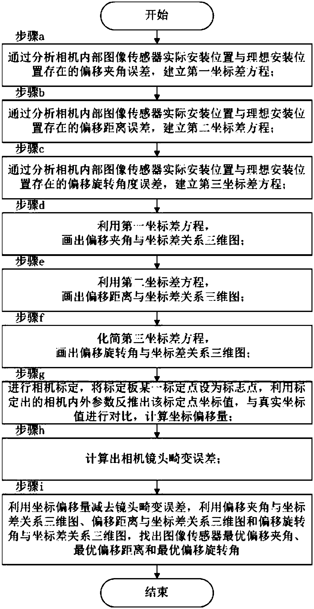
[0055]The method for separating the installation error of the image sensor inside the camera based on visual measurement in this embodiment, the flow chart is as follows figure 1 As shown, the method includes the following steps:

[0056] Step a, by analyzing the offset angle error between the actual installation position and the ideal installation position of the image sensor inside the camera, perform mathematical modeling, and establish the first coordinate difference equation between the actual imaging point and the ideal imaging point in the image sensor;

[0057] Step b, by analyzing the offset distance error between the actual installation position and the ideal installation position of the image sensor inside the camera, perform mathematical modeling, and establish a second coordinate difference equation between the actual imaging point and the ideal imaging point in the image sensor;

[0058] Step c, by analyzing the offset rotation angle error between the actual inst...

specific Embodiment 2

[0065] The method for separating the installation error of the camera internal image sensor based on visual measurement in this embodiment, on the basis of the specific embodiment 1, further defines step a as follows:

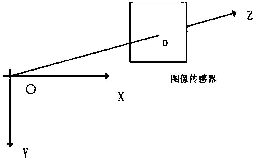
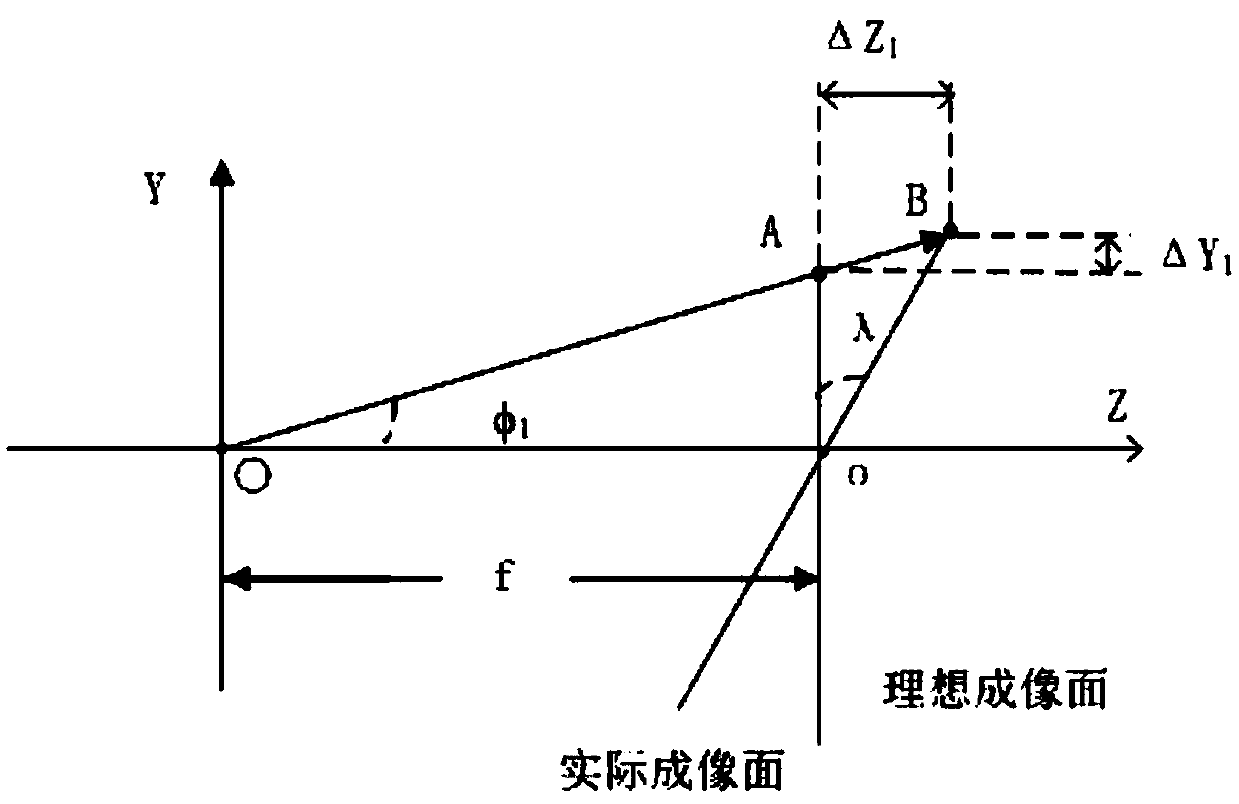
[0066] The camera coordinate system O-XYZ is established with the optical center of the camera as the origin, the Z axis coincides with the camera optical axis, the X and Y axes are parallel to the image sensor, o is the intersection point of the Z axis and the image sensor, and Oo is the focal length f of the camera; then the image Y-axis offset ΔY between the coordinates of the actual imaging point in the sensor and the coordinates of the ideal imaging point in the camera coordinate system 1 and the Z-axis offset ΔZ 1 They are:

[0067]

[0068]

[0069] In the formula, f represents the focal length of the camera, φ 1 Indicates the angle between the incident light and the z-axis, and λ indicates the angle between the actual installation position of th...

specific Embodiment 3

[0070] In this embodiment, the method for separating the installation error of the image sensor inside the camera based on visual measurement, on the basis of the specific embodiment 1, further defines step b as follows:

[0071] The camera coordinate system O-XYZ is established with the optical center of the camera as the origin, the Z axis coincides with the camera optical axis, the X and Y axes are parallel to the image sensor, and o is the intersection point of the Z axis and the image sensor; then the coordinates of the actual imaging point in the image sensor and Y-axis offset ΔY of the ideal imaging point coordinates in the camera coordinate system 2 and the Z-axis offset ΔZ 2 They are:

[0072] ΔY 2 =Δf·tanφ 2

[0073] ΔZ 2 =Δf

[0074] In the formula, Δf represents the deviation between the actual installation position of the image sensor and the ideal installation position, φ 2 Indicates the angle between the incident ray and the Z axis.


PUM


Abstract

The invention belongs to the field of optical measurement and visual sense detection, and particularly relates to a camera internal image sensor installation error separation method based on visual sense measurement. The method comprises steps of analyzing a deviation included angle error, a deviation distance error and a deviation rotation angle error between the actual installation position and the ideal installation position of a camera internal image sensor, and establishing a three coordinate difference equation of an actual imaging point and an ideal imaging point in the image sensor; drawing a relation three-dimensional graph between the deviation included angle error, the deviation distance error and the deviation rotation angle error and the coordinate difference; then carrying out camera calibration, and calculating a coordinate deviation amount; calculating a lens distortion error at the same time; and finally finding the deviation included angle optimal solution, a deviation distance optimal solution and a deviation rotation angle optimal solution of the image sensor. The method comprehensively considers the lens distortion error and the camera internal image sensor installation error, analyzes and verifies errors caused by the deviation between the actual installation position and the ideal installation position of the image sensor, and further provides the three-dimensional reconstruction precision.

Description

technical field [0001] The invention belongs to the field of optical measurement and visual detection, in particular to a method for separating installation errors of an image sensor inside a camera based on visual measurement. Background technique [0002] In recent years, machine vision technology and visual inspection technology have been widely used in many fields, such as aerial surveying and mapping, medical imaging, three-dimensional inspection of large and complex surfaces, automatic recognition and geometric measurement of mechanical parts, etc. Visual inspection can not only improve the detection accuracy, but also an effective solution when many conventional inspection methods cannot be realized. [0003] The acquisition of the image of the detected object is the basis of the research of visual inspection. The visual inspection system should be able to start from the image acquired by the industrial camera, and identify the object in the environment by determinin...

Claims


Application Information

Patent Timeline
Patent Type & Authority Patents(China)
IPC IPC(8): G01B11/24G01D3/032
CPCG01B11/24G01D3/032
Inventor 乔玉晶范宇琪曹岩谭世征
Owner HARBIN UNIV OF SCI & TECH
Why Eureka
Try Eureka