Dual-moving contact transmission device of circuit breaker

A transmission device and moving contact technology, applied to high-voltage air circuit breakers, circuits, electrical components, etc., can solve the problems of high cost, slow contact action, unstable performance, etc., and achieve convenient installation and maintenance and simple mechanism. , reliable performance

Inactive Publication Date: 2017-03-15
CHINA XD ELECTRIC CO LTD
View PDF4 Cites 9 Cited by
  • Summary
  • Abstract
  • Description
  • Claims
  • Application Information

AI Technical Summary

Problems solved by technology

[0003] Among the existing double-acting ceramic column circuit breakers, the high-voltage AC circuit breaker with a voltage level of 252kV has a high cost

Method used


Image

  • Dual-moving contact transmission device of circuit breaker
  • Dual-moving contact transmission device of circuit breaker
  • Dual-moving contact transmission device of circuit breaker

Examples


example 1

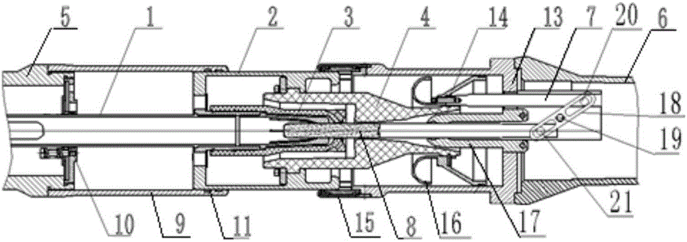
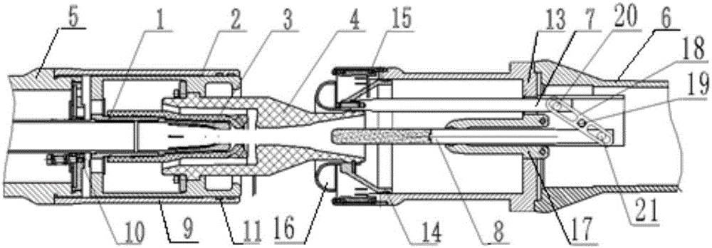
[0029] The present invention is a double-moving contact transmission device of a circuit breaker. The first pull rod 1, the cylinder 2, the first arc contact 3, the spout 4, and the second pull rod 7 are connected as a whole, and are limited by the guide, so they can only move horizontally and in phase. . The first fixed pivot pin 20 , the second fixed pivot pin 19 , and the third fixed pivot pin 21 are connected through a transmission connecting plate 18 , and the transmission connecting plate 18 can rotate around the second fixed pivot pin 19 . The second arcing contact 8 can move horizontally.

[0030] The first pull rod 1 is restricted by the first guide end plate 10 and can only move in the horizontal direction. The spout 4 is limited by the cone support 14 and can only move in the horizontal direction. The second pull rod 7 is restricted by the second conductor 13 and can only move in the horizontal direction. The structure of transmission connecting plate 18 is that ...

example 2

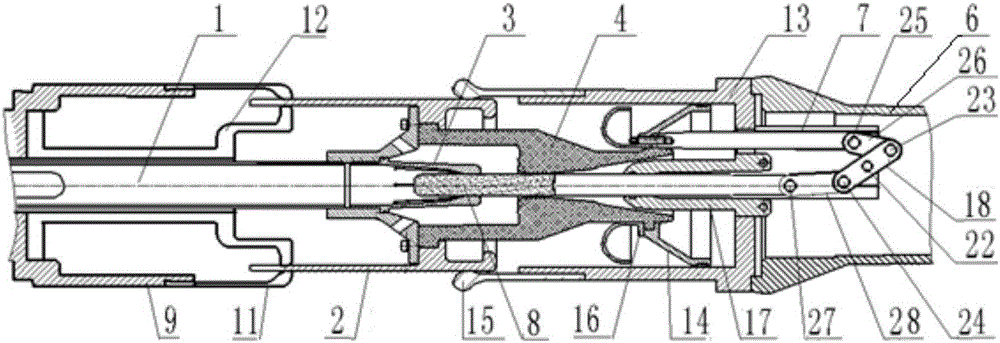
[0035] The invention is a double-action contact transmission device of a circuit breaker. The first pull rod 1, the cylinder 2, the first arc contact 3, the nozzle 4, and the second pull rod 7 are connected as a whole, and are limited by the guide, so they can only move horizontally. The first pivot pin 25, the first connecting plate 26, the second pivot pin 23, the transmission connecting plate 18, the third pivot pin 22, the fourth pivot pin 24, the second connecting plate 28, and the fifth pivot pin 27 form a reverse transmission device.

[0036] The first pull rod 1 is limited by the first conductor 9 and the piston 12 and can only move horizontally. The piston 12 is fixed on the first conductor 9, and when the cylinder 2 moves to the left, the piston 12 compresses the gas, and the gas is discharged into the nozzle 4 through the hole on the supporting member. The first contact finger 11 is fixedly connected to the first conductor 9 by screwing. The first contact finger 1...


PUM


Abstract

The invention provides a dual-moving contact transmission device of a circuit breaker. The device has advantages of fast relative speed of contacts, low operation power of the mechanism, and low product cost. The dual-moving contact transmission device comprises a first connecting terminal and a second connecting terminal, a first contact assembly, a second arc contact, and a reversed transmission unit, wherein the first connecting terminal and the second connecting terminal are arranged coaxially. The first contact assembly includes a first pull rod, an air cylinder, a first arc contact, a nozzle, and a second pull rod, wherein the units are connected successively into one; one end of the reversed transmission unit is connected with the second pull rod and the other end is connected with a driving terminal of the second arc contact; the first pull rod is used for power inputting; and the reversed transmission unit is used for transmitting the motion and the force of the first pull rod to the second arc contact in parallel in a reversed manner. The horizontal motion of one pull rod is converted into horizontal motions of the two arc contacts. And the two arc contacts carry out opening or closing simultaneously, so that the relative speeds of the moving and static arc contacts increase and the operation power of the mechanism is reduced obviously.

Description

technical field [0001] The invention relates to the field of high-voltage electric switches, in particular to a double-action contact transmission device of a circuit breaker. Background technique [0002] With the rapid development of my country's power industry, the economic requirements for power transmission and distribution are also increasing. Porcelain column AC circuit breakers mainly have two functions of control and protection in the power grid. The first is the control function. According to the operation needs of the power grid, a part of the power equipment or line is put into or out of operation with a high-voltage circuit breaker. The second is the protection function. When the power equipment or equipment fails, the high-voltage circuit breaker can quickly remove the faulty part from the power grid to ensure the normal operation of the fault-free part of the power grid. In short, the high-voltage circuit breaker can break, close and carry the normal current...

Claims


Application Information

Patent Timeline
IPC IPC(8): H01H33/91
CPCH01H33/91
Inventor 古王荣
Owner CHINA XD ELECTRIC CO LTD
Why Eureka
Try Eureka