Contact switching device

A technology of switching devices and contacts, which is applied in the directions of detailed information of electromagnetic relays, relays, electrical components, etc., can solve the problems of deviation of action characteristics, high positioning accuracy, assembly errors, etc., and achieve low manufacturing costs, simple assembly operations, and difficult The effect of assembly error

Active Publication Date: 2017-03-15
ORMON CORPORATION
View PDF4 Cites 10 Cited by
  • Summary
  • Abstract
  • Description
  • Claims
  • Application Information

AI Technical Summary

Problems solved by technology

[0008] In addition, in the above-mentioned assembly work, assembly errors are likely to occur, and it is difficult to o

Method used


Image

  • Contact switching device
  • Contact switching device
  • Contact switching device

Examples


Example Embodiment

[0043] according to Figure 1 to Figure 17 The accompanying drawings illustrate the case where the contact opening and closing device of the embodiment of the present invention is applied to a sealed electromagnetic relay.

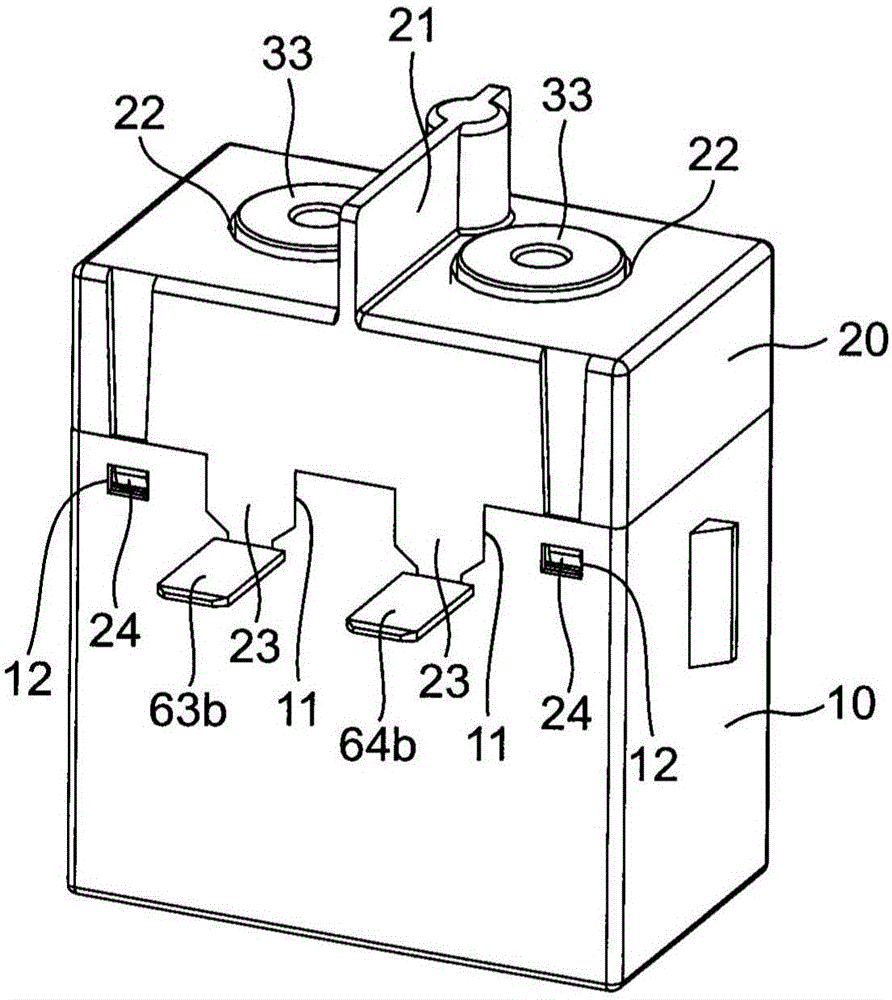
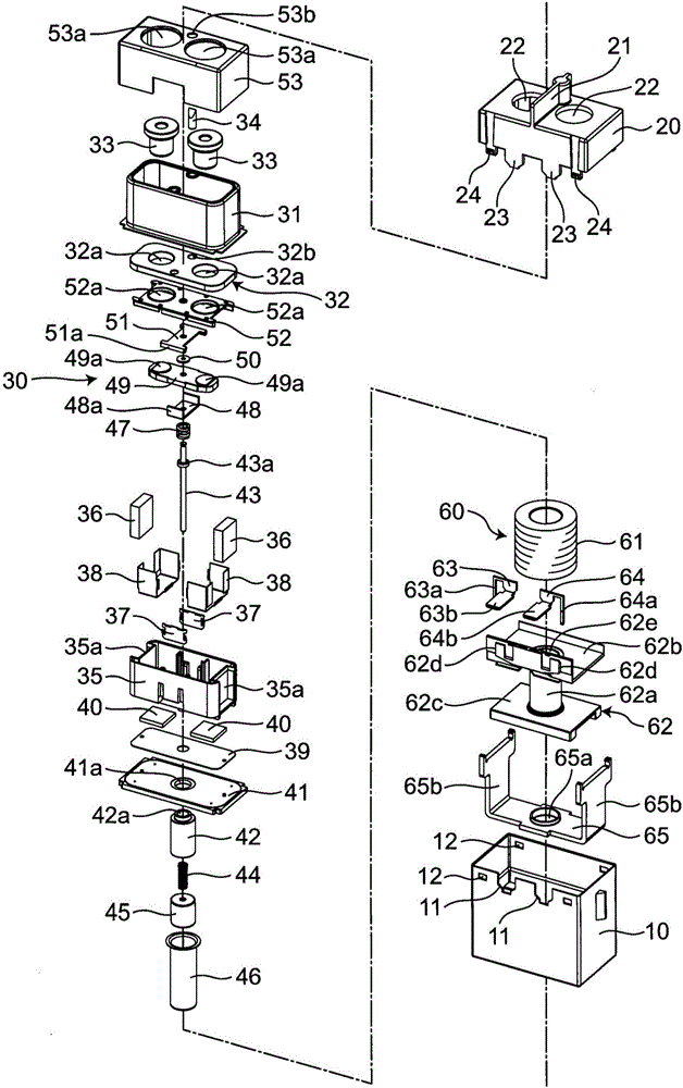
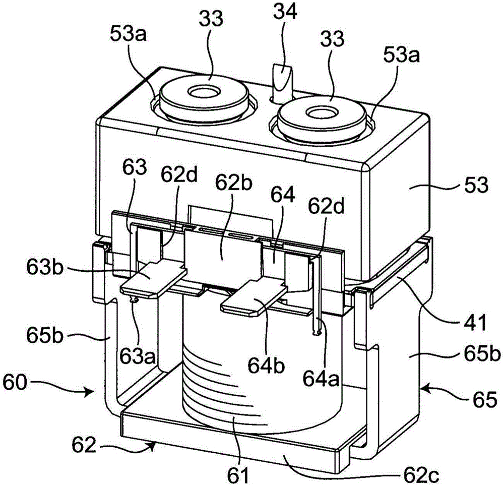
[0044] The sealed electromagnetic relay of this embodiment is configured to include at least an electromagnet unit 60, a holder 35, a movable shaft 43, a movable contact piece 49, a movable yoke 48, a pair of fixed contacts 33a, and a fixed yoke 51. Specifically, such as Figure 1 to Figure 5 As shown, an outer cover 20 is assembled on the housing 10 to form a housing, and a contact mechanism unit 30 and an electromagnet unit 60 are assembled in the housing.

[0045] Such as figure 2 As shown, the housing 10 is an insulating resin molded product with a substantially quadrangular box shape, and a set of notches 11 is formed on one side of the opening edge. In addition, the housing 10 is provided with a total of two pairs of locking holes 12 at both ends of the...


PUM


Abstract

There is provided a contact switching device which has high productivity and in which operation characteristics hardly vary. The contact switching device includes an electromagnetic unit (60), a holder (35), a movable shaft (43), a movable yoke (48), a movable contact piece (49) having movable contacts (49a) at both ends, fixed contacts (33a), and a fixed yoke (51). At the time of excitation of the electromagnetic unit (60), the movable shaft (43) moves to the holder (35) side along a direction of an axis center. A magnetic circuit is formed of the fixed yoke (51) and the movable yoke (48) due to a magnetic field generated by a current that flows into the movable contact piece (49) as a result of the movable contacts (49a) coming into contact with the fixed contacts (33a). The movable yoke (48) is then attracted to the fixed yoke (51).

Description

technical field [0001] The present invention relates to a contact switching device, in particular to a contact switching device suitable for a power load relay or an electromagnetic switch. Background technique [0002] Conventionally, as a contact opening and closing device, for example, Patent Document 1 Figure 5 As shown in (a), a pair of through-holes 61a are provided on the upper surface of the container 61 made of a heat-resistant material such as ceramics. Furthermore, the fixed terminals 33 and 33 are respectively inserted into the pair of said through-holes 61a, and are soldered. Furthermore, a yoke body 63 is fixed inside the upper surface of the container 61 located between the pair of fixed terminals 33 , 33 . The yoke body 63 has a substantially rectangular parallelepiped shape made of a magnetic material such as mild steel. [0003] Furthermore, when the movable contacts 34 , 34 provided on the movable contact 35 come into contact with the fixed contacts 32 ...

Claims


Application Information

Patent Timeline
IPC IPC(8): H01H50/54H01H50/16
CPCH01H50/16H01H50/54H01H50/20H01H50/36H01H50/38
Inventor 广木和亲森真吾
Owner ORMON CORPORATION
Why Eureka
Try Eureka