Multi-layer planar antenna array

A technology of planar antennas and arrays, applied in antenna arrays, antennas, slot antennas, etc., can solve the problems of high processing cost of feed structure, surface wave strength of patch antenna, narrow bandwidth of slot antenna array, etc., and achieve performance and cost optimization , wide bandwidth, high gain effect

Active Publication Date: 2017-03-15
GUANGDONG SHENGLU TELECOMM TECH +1
View PDF3 Cites 20 Cited by
  • Summary
  • Abstract
  • Description
  • Claims
  • Application Information

AI Technical Summary

Benefits of technology

This patented solution helps reduce signal losses while still providing good radio frequency (RF) reception capabilities at microwave frequencies. It achieves this through utilizing two different networks - one uses dual-layers or longer wavelength waves for better performance but cheaper materials like silicon carbide), and another on top of it called an integrating airwaveguide system. By combining these techniques together, we aimed towards improving wireless communication devices' efficiency and reducing their manufacturing costs.

Problems solved by technology

This patented describes different ways how we can improve the design or manufacture of an mmWave radio device by optimizing the placement of various electronic devices within it's housing. One method involves dividing up some elements (like power amplifiers) from each other based on specific requirements like signal quality, efficiency, size, weight, thickness). Another approach suggests adding extra circuitry outside the main body of the radar itself instead of just placing them inside. These techniques aim at improving overall functionality without sacrificing any important factors like electrical properties or physical dimensions that affect the performance of the radiating element(s), which makes optimization challenges.

Method used


Image

  • Multi-layer planar antenna array
  • Multi-layer planar antenna array
  • Multi-layer planar antenna array

Examples


Embodiment Construction

[0033] The technical solution will be described in detail below in conjunction with specific embodiments.

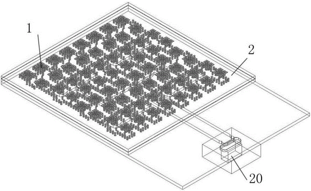
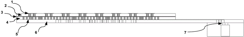
[0034] like Figure 1-Figure 2 As shown, the present invention is a multilayer planar antenna array, which includes several layers of dielectric plates integrated with double-layer feed networks and integrated air waveguides and interlayer metal plates arranged between adjacent two layers of dielectric plates, Slot coupling is used between layers; the upper layer is 2×4 sub-array, the middle and lower layers of the double-layer feed network are 4×2 air waveguide power distribution network, and the upper layer is 2×4 sub-array, using SIW feed network, dielectric board and inter-layer The metal plates are laminated to form a complete antenna. This combination makes a common metal partition between layers, saving costs.

[0035] The multi-layer antenna array in this embodiment is a 7-layer combined structure.

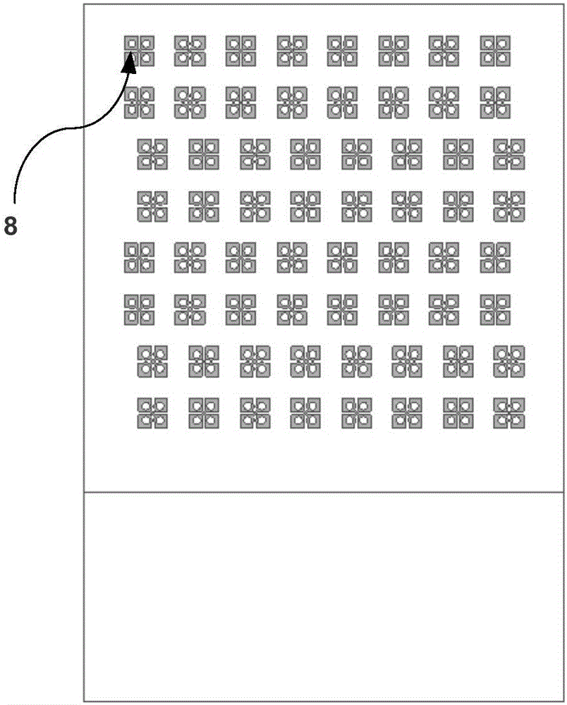
[0036] like image 3 As shown, in the first dielectric board...


PUM

PropertyMeasurementUnit
Thicknessaaaaaaaaaa
Lengthaaaaaaaaaa
Thicknessaaaaaaaaaa

Abstract

The invention discloses a multi-layer planar antenna array. The multi-layer planar antenna array is characterized by comprising multiple layers of dielectric plates and interlayer metal plates, wherein each layer of dielectric plate is integrated with a double-layer feed network (including an integrated air waveguide) and one part of antenna structure separately; one interlayer metal plate coats the part between two adjacent layers of dielectric plates; the layers are coupled by using gaps; a lower layer in each double-layer feed network is an air waveguide power division network and an upper layer is an SIW feed network; and the dielectric plates and the interlayer metal plates are laminated into a complete antenna. The multi-layer planar antenna array is simple in structure; compared with the same type of products, the multi-layer planar antenna array has the advantages of being low in transmission loss, large in bandwidth, easy to process and high in gain; and the cost is reduced while the performance is kept.

Description


Claims


Application Information

Patent Timeline
Owner GUANGDONG SHENGLU TELECOMM TECH
Why Eureka
Try Eureka