Pulsed laser diode drive circuit

A pulsed laser and drive circuit technology, applied to circuits, lasers, laser components, etc., can solve the problems of uncertain duty cycle, variable frequency, low precision and unstable driving source signal, etc.

Pending Publication Date: 2017-03-15
HARGLO APPLIED LASER TECH INST CO LTD
View PDF4 Cites 6 Cited by
  • Summary
  • Abstract
  • Description
  • Claims
  • Application Information

AI Technical Summary

Problems solved by technology

[0004] In view of this, the present invention aims to propose a pulsed laser diode drive circuit, which can provide a pulsed laser diode drive circuit with high precision, adjustable frequency and duty cycle, and can better overcome the pulsed laser diode drive source signal. Problems such as low accuracy, instability, variable frequency, and uncertain duty cycle

Method used


Image

  • Pulsed laser diode drive circuit
  • Pulsed laser diode drive circuit

Examples


Embodiment Construction

[0019] It should be noted that, in the case of no conflict, the embodiments of the present invention and the features in the embodiments can be combined with each other.

[0020] In describing the present invention, it should be understood that the terms "center", "longitudinal", "transverse", "upper", "lower", "front", "rear", "left", "right", " The orientations or positional relationships indicated by "vertical", "horizontal", "top", "bottom", "inner" and "outer" are based on the orientations or positional relationships shown in the drawings, and are only for the convenience of describing the present invention and Simplified descriptions, rather than indicating or implying that the device or element referred to must have a particular orientation, be constructed and operate in a particular orientation, and thus should not be construed as limiting the invention. In addition, the terms "first", "second", etc. are used for descriptive purposes only, and should not be understood ...


PUM


Abstract

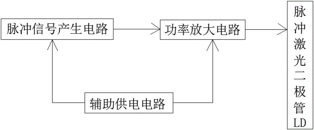
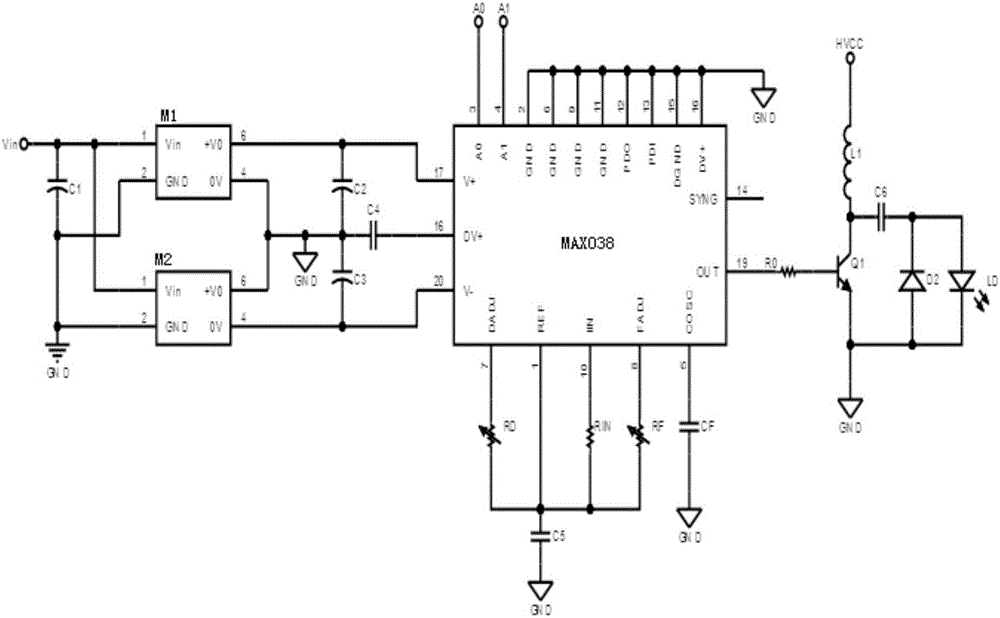
The invention provides a pulsed laser diode drive circuit, which comprises a pulse signal generation circuit, a power amplifier circuit, a pulsed laser diode LD and an auxiliary power supply circuit, wherein the pulse signal generation circuit is used for generating an electric pulse signal and is provided with a pulse generator with an optional waveform and adjustable frequency and duty ratio; a pulse signal generated by the pulse signal generation circuit is used for exciting the next stage of power amplifier circuit; the power amplifier circuit amplifies the previous stage of electric pulse signal and the amplified signal is used for driving the pulsed laser diode LD to normally work; and the auxiliary power supply circuit is used for supplying the pulse signal generation circuit and the power amplifier circuit with electricity. The pulsed laser diode drive circuit has the beneficial effects that the pulsed laser diode drive circuit with high precision and adjustable frequency and duty ratio can be provided; and the problems that a pulsed laser diode drive source signal is low and unstable in precision, variable in frequency and uncertain in duty ratio are relatively well solved.

Description

technical field [0001] The invention belongs to the technical fields of lasers, laser radars, etc., and in particular relates to a pulsed laser diode driving circuit. Background technique [0002] With the increasing development and maturity of semiconductor laser technology, the use of laser diodes or laser diode arrays to replace traditional flash lamps and ion pump sources has become the development direction of solid-state laser technology. Diode lasers are widely used in national defense, scientific research, medical treatment, communication and other fields due to their advantages of small size, light weight and long working life. With the continuous improvement of laser performance, the performance of laser diode drive power has also been continuously improved. The state of the output light of the laser diode is directly determined by the driving circuit, so more stringent requirements are put forward for the supporting driving circuit. The laser diode drive circuit...

Claims


Application Information

Patent Timeline
Patent Type & Authority Applications(China)
IPC IPC(8): H01S5/042
CPCH01S5/0428
Inventor 张贵艳刘博许东晖
Owner HARGLO APPLIED LASER TECH INST CO LTD
Why Eureka
Try Eureka