

Valve control unit of automatic control system of uranium enrichment plant
A concentration device and valve control technology, which is applied in the direction of valve devices, electric controllers, valve operation/release devices, etc., can solve problems such as burning out valves and damaging control units, and achieves easy debugging, low cost, and significant economic benefits Effect
Active Publication Date: 2010-09-08
CNNC LANZHOU URANIUM ENRICHMENT
View PDF0 Cites 2 Cited by
- Summary
- Abstract
- Description
- Claims
- Application Information
AI Technical Summary
Problems solved by technology
Method used
View moreImage
Smart ImageViewing Examples

Examples
Embodiment Construction
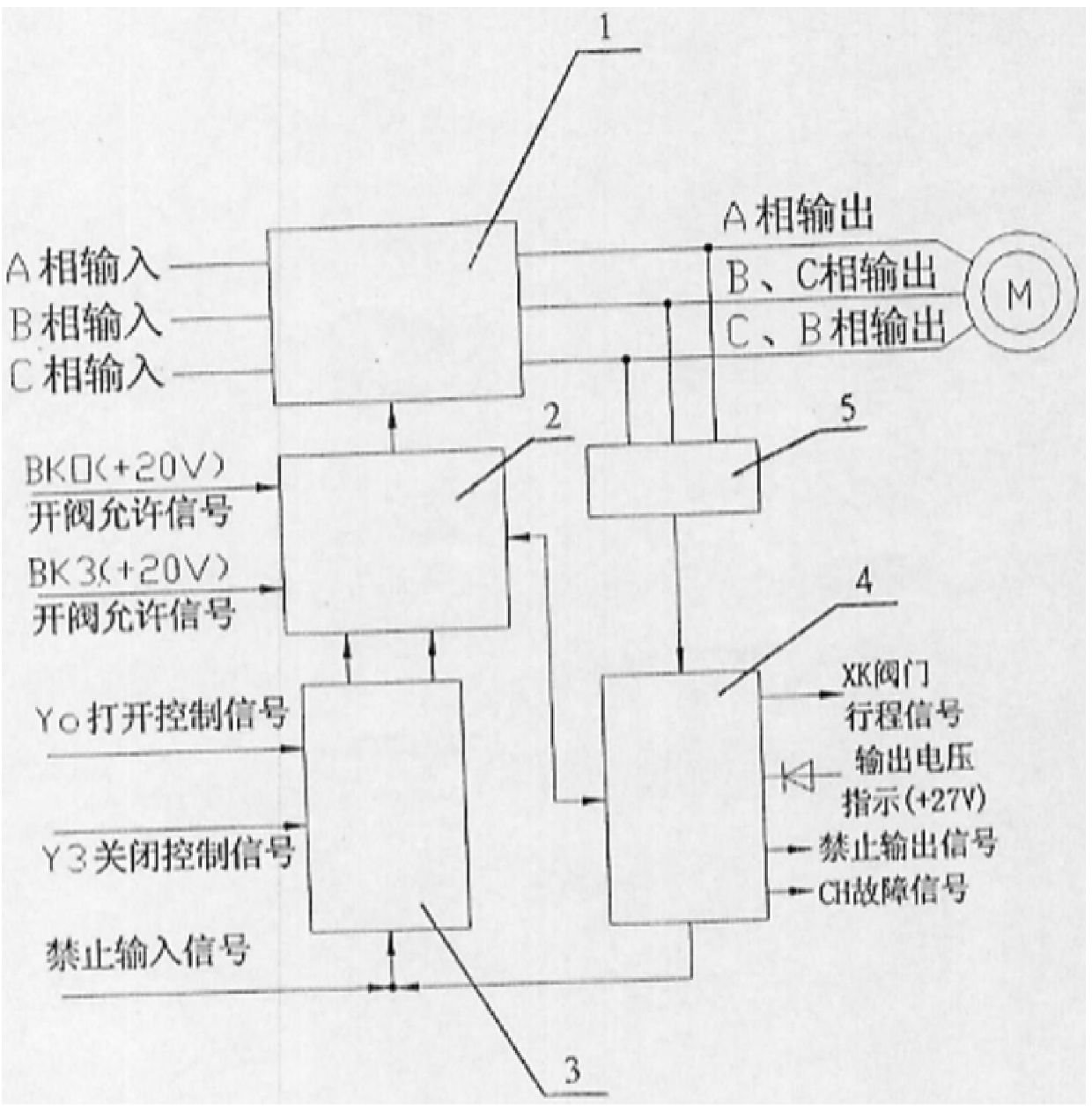
[0014] When the prohibition input signal is used, the prohibition signal will also be generated to prohibit the control of the Y0, Y3 signal.
Login to View More PUM
 Abstract
The invention belongs to the technical field of automatic control, and in particular relates to a valve control unit of an automatic control system in a uranium enrichment device manufactured by a centrifugal method. It includes a solid-state relay control circuit for controlling the solid-state relay switching circuit. The solid-state relay control circuit is respectively connected with a control chain circuit for discriminating control signals and a protection circuit for protecting the valve motor when a mechanical failure occurs in the valve. The protection circuit is connected with the valve motor. The output detection circuit used to detect the output signal is connected; the solid-state relay control circuit is connected to the valve terminal switch to receive the valve opening or closing permission signal issued by the valve terminal switch, and the control chain circuit is connected to the main control system to receive the signal from the main control system. External control signal, according to the external control signal, the valve control unit can connect the load motor to the circuit under the condition that the valve opening permission signal exists. The valve control unit has low cost, high reliability, easy operation and maintenance.
Description
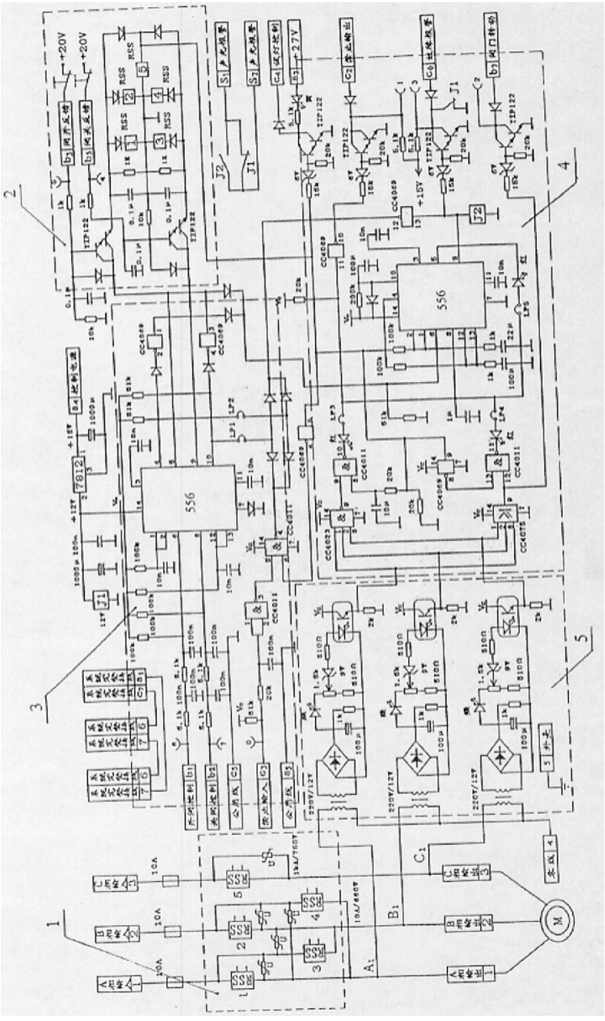
Valve control unit of automatic control system of uranium enrichment plant Technical field The invention belongs to the technical field of automatic control, be specifically related to a kind of automatic control system in the uranium enrichment device manufactured by centrifugation valve control unit. Background technique What my country used in the past in centrifugal method to manufacture enriched uranium plant automatic control system is the valve imported from Russia Control unit, which belongs to the control technology in the early 1980s, mainly consists of thyristor switch, oscillator, rectifier, output It is composed of voltage comparator, transformer and Russian special logic circuit. where the oscillator is used to output the controlled SCR control Signals, transformers and rectifiers are used to convert the output voltage of the thyristor to the corresponding DC voltage, the logic control circuit and The comparator is used to ensure that when there is an ...
Claims
Login to View More Application Information
Patent Timeline
 Patent Type & AuthorityPatents(China)
IPC IPC(8): F16K31/04G05B11/01
Inventor段东权李乡伟
OwnerCNNC LANZHOU URANIUM ENRICHMENT