Clamping method for wire pipe welding edge
A clamping method and wire tube technology, applied in the direction of clamping device, clamping, support, etc., can solve the problems of pipe fittings falling, pipe fittings clamping loose, large interaction force, etc., to ensure efficiency and improve clamping force , the effect of improving the service life
- Summary
- Abstract
- Description
- Claims
- Application Information
AI Technical Summary
Problems solved by technology
Method used
Image
Examples
Embodiment 1
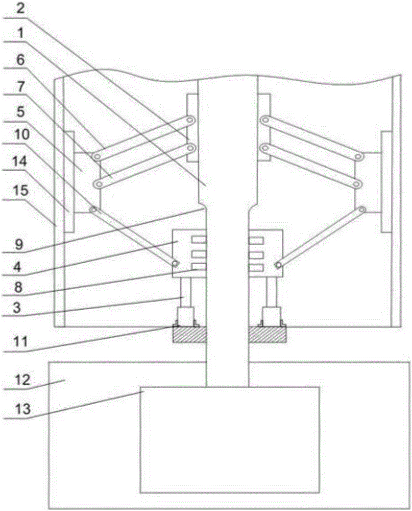
[0021] like figure 1 As shown, a groove processing device for a pipe fitting 15 in the present invention includes the following steps. First, the pipe fitting 15 is set outside the fixed rod 1, and the cylinder 3 is adjusted so that the output end moves upward to drive the sliding cylinder 4 to rise, and the lower rod drives the swing arm 5 Fitted with the inner wall of the pipe fitting 15, the fixed cylinder 2 is fixedly arranged on the upper end of the fixed rod 1, and provides strong support for the swing arm 5 through the upper swing rod 6 and the lower swing rod 7, and the driving motor 13 starts to drive the fixed rod 1 to rotate, When the force exerted by the swing arm 5 on the inner wall of the pipe fitting 15 reaches the maximum, the cutting tool on the lathe starts to rotate the edge of the pipe fitting 15, and the swing arm 5 which can be adjusted arbitrarily can be used for groove processing with pipe fittings 15 of various diameters. ; Wherein, the support frame 1...
Embodiment 2
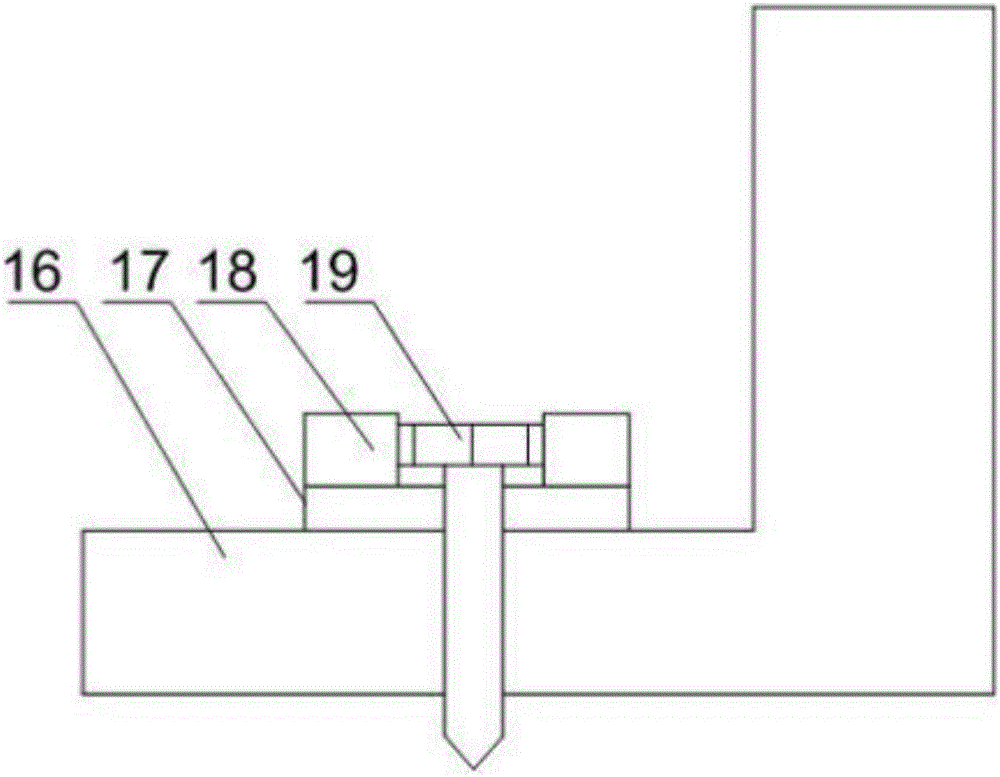
[0024] like figure 2 As shown, on the basis of Embodiment 1 in this embodiment, L-shaped baffles 16 are also installed at both ends of the cylinder 3, through holes are opened on the retaining ring 11 and the L-shaped baffle 16, and the retaining ring 11 The L-shaped baffle plate 16 is connected with the L-shaped baffle plate 16 through the through hole through the screw 19, and a washer 17 arranged on the through hole is also included, and an annular protrusion 18 is installed on the washer 17. The retaining ring 11 rotates together with the fixed rod 1, and the cylinder 3 will loosen during the non-stop rotation. The L-shaped baffle 16 clamps both ends of the cylinder 3, and the L-shaped baffle 16 and the retaining ring 11 are connected by screws 19. For connection, the annular protrusion 18 can well protect the screw 19 from external influences and improve the service life of the present invention.
Embodiment 3
[0026] like figure 1 As shown, in this embodiment, on the basis of Embodiment 1, the end face of the swing arm 5 away from the end of the fixed rod 1 is an arc surface; the arc surface is provided with a backing plate 14, and the arc of the backing plate 14 The surface area is greater than that of the arc surface of the swing arm 5; the roller 8 is a rubber wheel. When clamping the inner wall of the pipe fitting 15, the swing arm 5 is in contact with the inner wall of the pipe fitting 15, and the swing arm 5 on the arc surface can be completely attached to the inner wall of the pipe fitting 15, thereby improving the clamping force of the swing arm 5 on the pipe fitting 15; The backing plate 14 provided on the top can further increase the contact area with the inner wall of the pipe fitting 15 to ensure the stability of clamping.
[0027] Preferably, the rubber wheel can be deformed to a certain extent after the sliding cylinder 4 is subjected to stress, and the reaction force...
PUM
 Abstract
Description
Claims
Application Information
 - R&D
- Intellectual Property
- Life Sciences
- Materials
- Tech Scout
- Unparalleled Data Quality
- Higher Quality Content
- 60% Fewer Hallucinations
Browse by: Latest US Patents, China's latest patents, Technical Efficacy Thesaurus, Application Domain, Technology Topic, Popular Technical Reports.
© 2025 PatSnap. All rights reserved.Legal|Privacy policy|Modern Slavery Act Transparency Statement|Sitemap|About US| Contact US: help@patsnap.com


