Bag clamping device realizing movable clamping through bag sleeving ring

A clamping device and bagging technology, applied in the field of mechanical spare parts, can solve the problems of huge workload, manual labor, and waste of labor for grain peeling workers, avoiding multiple transfers, stable clamping process, and convenient installation and maintenance. Effect

Inactive Publication Date: 2017-03-22
重庆市江津区前进焊接材料厂
View PDF5 Cites 5 Cited by
  • Summary
  • Abstract
  • Description
  • Claims
  • Application Information

AI Technical Summary

Problems solved by technology

[0003] In this process, if the amount of transshipment is large, it will cause a lot of physical labor and cause a huge workload for the peeling staff.
At the same ti

Method used


Image

  • Bag clamping device realizing movable clamping through bag sleeving ring
  • Bag clamping device realizing movable clamping through bag sleeving ring

Examples


Embodiment 1

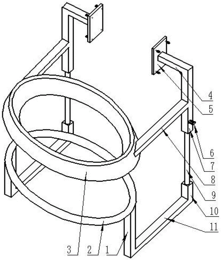
[0024] like figure 1 As shown, in order to overcome the defects of the prior art, the present invention provides a pocket clamping device that utilizes the bagging ring to move and clamp, including a first bracket 1, a fourth bracket 7, a fifth bracket 4, and a fixing plate 5 , clamping ring bracket 8, piston rod 9, third bracket 10 and second bracket 11; fixed plate 5 connects one end of the fifth bracket 4, and the other end of the fifth bracket 4 connects one end of the fourth bracket 7, and the fourth bracket The middle part of 7 is connected with one end of the clamping ring bracket 8, the other end of the clamping ring bracket 8 is connected with the clamping ring 3, the other end of the fourth bracket 7 is provided with a hydraulic cylinder, and the piston of the hydraulic cylinder is connected with one end of the piston rod 9, The other end of piston rod 9 connects an end of the third support 10, and the other end of the third support 10 connects an end of the second s...

Embodiment 2

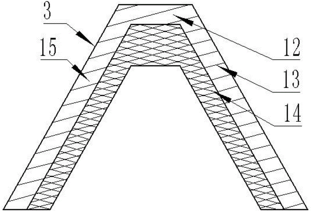
[0028] This embodiment is further improved on the basis of embodiment 1, as figure 1 , figure 2 As shown, the clamping ring 3 includes a transverse plate 12, an outer plate 13 and an inner plate 15, the transverse plate 12 is arranged on the upper part of the outer plate 13 and the upper part of the inner plate 15, and the angle between the outer plate 13 and the transverse plate 12 is equal to the inner The angle between the plate 15 and the transverse plate 12, the transverse plate 12, the outer plate 13 and the inner plate 15 form an annular accommodation chamber with an opening, the cross section of the annular accommodation chamber is an isosceles trapezoid, and the opening position of the annular accommodation chamber On the long base of an isosceles trapezoid. This setting can make the clamping ring 3 cooperate with the bagging ring 2 whose cross-sectional size is within a certain range, so that the versatility of the clamping ring 3 is better; at the same time, the o...


PUM


Abstract

The invention discloses a bag clamping device realizing movable clamping through a bag sleeving ring. The bag clamping device comprises first brackets, fourth brackets, fifth brackets, fixing plates, clamping ring supports, piston rods, third brackets and second brackets, wherein each fixing plate is connected with one end of the corresponding fifth bracket, the other end of the fifth bracket is connected with one end of the corresponding fourth bracket, the middle of the fourth bracket is connected with one end of the corresponding clamping ring support, the other end of the clamping ring support is connected with a clamping ring, a hydraulic cylinder is arranged at the other end of the fourth bracket, a piston of the hydraulic cylinder is connected with one end of the corresponding piston rod, the other end of the piston rod is connected with one end of the corresponding third bracket, the other end of the third bracket is connected with one end of the corresponding second bracket, the other end of the second bracket is connected with one end of the corresponding first bracket, and the other end of the first bracket is connected with the lower end of the bag sleeving ring. Materials required to be bagged can be directly discharged into a bag, repeated transfer is avoided, and the labor intensity is reduced; meanwhile, the contact areas of the bag sleeving ring and the clamping ring with the bag are larger when the bag sleeving ring and the clamping ring clamp the bag, and the bag can be clamped stably.

Description

technical field [0001] The invention relates to the technical field of mechanical parts, in particular to a pocket clamping device which uses a pocket ring to move and clamp. Background technique [0002] In commonly used mechanical equipment, there is no corresponding pocket holding device for the outlet of the processed items, but the processed items need to be bagged. Taking the rice peeling machine as an example, the rice outlet does not have a corresponding pocket holding device. In order to put the rice into the pocket, two barrel-shaped transfer devices are needed to load the rice at the rice outlet in turn, and then pour it into the pocket. [0003] In this process, if the amount of transshipment is large, it will cause a lot of physical labor and cause a huge workload to the peeling staff. At the same time, in the process of pouring the rice into the pocket, others need to open the opening of the pocket, so additional workers are needed, resulting in a waste of man...

Claims


Application Information

Patent Timeline
IPC IPC(8): B65B43/54
CPCB65B43/54
Inventor 温晓琳
Owner 重庆市江津区前进焊接材料厂
Why Eureka
Try Eureka