
Stopper

A technology of blocker and blocker, applied in the direction of conveyor objects, transportation and packaging, can solve the problems of inability to use, low work efficiency, unfavorable economic efficiency, etc., to reduce the height of the body, reduce the space occupied, and improve work efficiency Effect

Active Publication Date: 2017-03-22
GUANGDONG JATEN ROBOT & AUTOMATION
View PDF15 Cites 18 Cited by
  • Summary
  • Abstract
  • Description
  • Claims
  • Application Information

AI Technical Summary

Problems solved by technology

[0003] At present, in the field of assembly line transportation, there are two most common stoppers, namely vertical stopper and horizontal stopper. The height of the body of the device is high, and it cannot be used in lower height conveying applications
For mobile equipment, the cylinder carrying compressed air will increase the space occupied by the mobile equipment; and the work efficiency of using the pneumatic control blocker switch to start is low, which is not conducive to the economic efficiency of the enterprise.

Method used


Image

  • Stopper
  • Stopper
  • Stopper

Examples


Embodiment Construction

[0024] A preferred embodiment of the present invention will be described below with reference to the accompanying drawings.

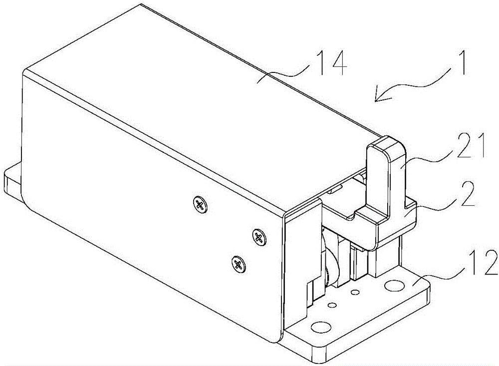
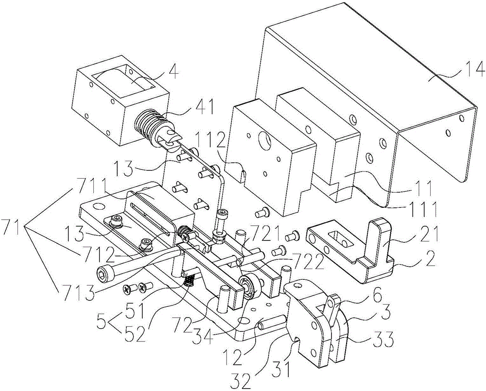
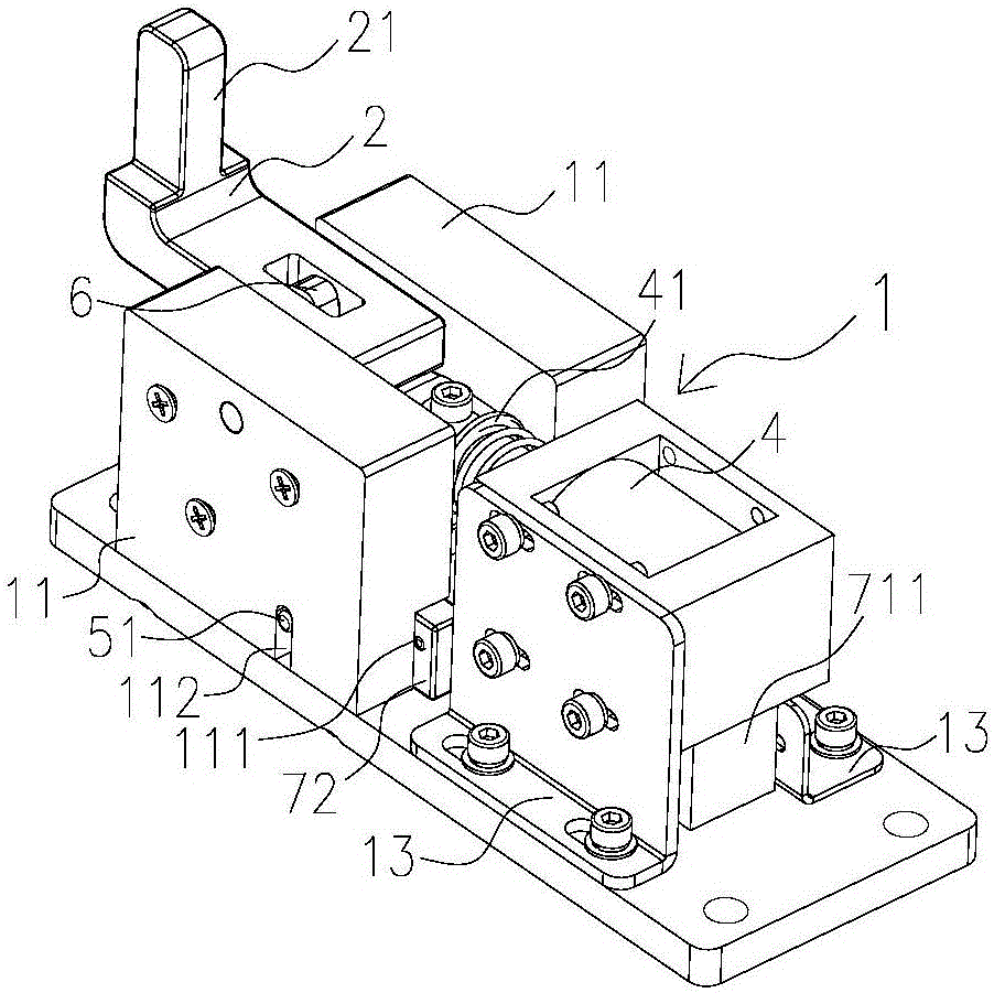
[0025] see Figures 1 to 6 , the stopper of the present invention includes a frame 1, a stopper 2, a slide seat 3, a first traction electromagnet 4, a first reset mechanism 41 and a locking mechanism 5, and the head end of the stopper 2 is connected to the frame 1 is hinged, the tail of the blocking member 2 is provided with a blocking portion 21, the blocking member 2 is hinged to the sliding seat 3 through the connecting rod 6, and the traction rod of the first traction electromagnet 4 is connected to the sliding seat 3; The first traction electromagnet 4 drives the slide seat 3 to move to the first traction electromagnet 4 side to make the blocking part 21 turn down to realize storage. When the slide seat 3 moves to the locked position, the locking mechanism 5 locks the slide seat 3 and unlocks the locking mechanism. 5. The first reset mechanism 41 ...


PUM


Abstract

The invention discloses a stopper. The stopper comprises a machine frame, a stop component, a sliding base, a first drawing electromagnet, a first resetting mechanism and a locking mechanism, wherein the head end of the stop component is connected to the machine frame in a hinged mode, a stop part is arranged at the tail of the stop component, the stop component is connected to the sliding base through a connecting rod in a hinged mode, and a drawing bar of the first drawing electromagnet is connected to the sliding base. The first drawing electromagnet draws the sliding base to move so that the stop part can be overturned downwards to realize the storage function, the locking mechanism locks the sliding base when the sliding base moves to a locking position, and the first resetting mechanism pushes the sliding base to be reset so that the stop part can be overturned upwards and exposed after the locking mechanism is unlocked. Compared with existing products, the stopper has the advantages that the drawing electromagnet, the first resetting mechanism and the locking mechanism are designed, the sliding base is driven to move, the stop component is controlled to be overturned upwards, and therefore the stop function or the storage function can be realized; an electric mode replaces a pneumatic mode for controlling the stop component, the body height of the stopper is lowered, and therefore the stop function of the stopper can be realized at a low height; and an electromagnet control device is adopted, and therefore the work efficiency is high, use is convenient and the work efficiency is improved.

Description

technical field [0001] The invention belongs to the technical field of automatic logistics transportation, and in particular relates to a stopper. Background technique [0002] With the development of science and technology, the automatic conveying system is more and more widely used for the transportation of logistics goods. The stopper is a product developed for the automatic conveying system, which can conveniently and reliably control the transportation and stop of the operation fixture and products. And act as a limit stop. [0003] At present, in the field of assembly line transportation, there are two most common stoppers, namely vertical stopper and horizontal stopper. The height of the body of the device is relatively high, and it cannot be used in conveying applications with a lower height. For mobile equipment, the cylinder carrying compressed air will increase the space occupied by the mobile equipment; and the work efficiency of using the pneumatic control blo...

Claims


Application Information

Patent Timeline
Patent Type & Authority Applications(China)
IPC IPC(8): B65G47/88
CPCB65G47/8815
Inventor 崔俊健杨振华
Owner GUANGDONG JATEN ROBOT & AUTOMATION
Learn More