Annular rope weaving machine
A rope braiding machine and ring-shaped technology, which is applied in the field of ring rope braiding machines, can solve the problems such as the inability to continuously loop the braiding of the ring rope, and achieve the effects of saving manpower and material resources, high transmission precision, and safe and simple operation.
- Summary
- Abstract
- Description
- Claims
- Application Information
AI Technical Summary
Problems solved by technology
Method used
Image

Examples
Embodiment 1
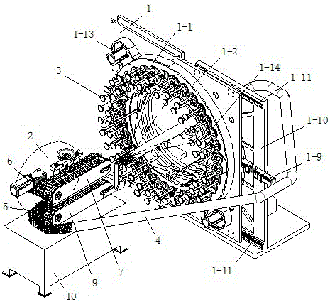
[0028] Embodiment 1: The braiding machine includes: a transmission device, a traction device, a spindle and a controller; There is a ring hole, and the ring hole is the working area; there is a traction device on the extension line of the ring center of the transmission device, and a sandwich is installed on the traction device, and the sandwich passes through the working area to form a complete ring; the controller controls the transmission device and Drive motor for traction unit.
[0029] The traction device includes: a traction motor 6, an upper traction roller 7, a lower traction roller 9 and a traction bracket 10; the traction motor 6 is connected with the upper traction roller 7, and the upper traction roller 7 and the lower traction roller 9 are installed oppositely and installed at the same time On the traction bracket 10.
[0030] The upper traction roller 7 and the lower traction roller 9 are the same, or are round rollers with rope grooves on the outer peripheral ...
Embodiment 2
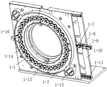
[0038] Embodiment 2: There are a plurality of static disk mounting holes 1-21 on the vertical plate 1-18, and a plurality of operating holes for installing the moving disk and the static disk are arranged around the working hole 1-20.
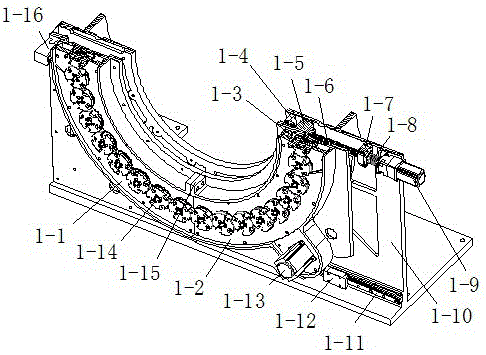
[0039] The moving disk 1-2 is a 1 / 4 circle of a complete ring assembled by the moving disk 1-2 and the static disk 1-1; the static disk 1-1 and the moving disk 1-2 are combined to form a complete The circular runway, when the size of the circular runway is large, in order to increase the driving force of the second motor 1-13 to drive the spindle dial, the static disc 1-1 and the moving disc 1-2 both include the upper disc and the lower disc And the second motor 1-13, the second motor is connected with the moving disk and the static disk through mechanical transmission respectively. The reciprocating transmission member 6 includes a rack 23 and a gear 24, the gear is fixed on the base plate 10, the connector is a solid block, one end of the rac...
Embodiment 3
[0041] Embodiment 3: The moving disk 1-2 is any radian of a complete ring assembled by the moving disk 1-2 and the static disk 1-1, and the moving disk is less than 90°. Others are the same as in Example 1.
PUM
 Abstract
Description
Claims
Application Information
 - Generate Ideas
- Intellectual Property
- Life Sciences
- Materials
- Tech Scout
- Unparalleled Data Quality
- Higher Quality Content
- 60% Fewer Hallucinations
Browse by: Latest US Patents, China's latest patents, Technical Efficacy Thesaurus, Application Domain, Technology Topic, Popular Technical Reports.
© 2025 PatSnap. All rights reserved.Legal|Privacy policy|Modern Slavery Act Transparency Statement|Sitemap|About US| Contact US: help@patsnap.com