
Gas well underground rotational flow atomization water drainage and gas recovery device

A drainage gas recovery and gas well technology, which is applied in wellbore/well components, production fluid, earthwork drilling and production, etc. It can solve the problems of gas wells not producing normally, gas wells stop production due to liquid accumulation, and gas well productivity is poor, so as to improve the flow state of the wellbore , clear water, increase the effect of gas production

Pending Publication Date: 2017-03-22
陕西圣润能源环保科技有限公司
View PDF6 Cites 4 Cited by
  • Summary
  • Abstract
  • Description
  • Claims
  • Application Information

AI Technical Summary

Problems solved by technology

The liquid carrying effect of the gas well is the best when the flow state of the wellbore is annular mist flow. In the middle and later stages of gas well production, the flow state of the wellbore is slug flow, stirring flow, and annular mist flow from bottom to top. The productivity of the gas well is poor and cannot reach When the liquid-carrying flow rate is critical, the bottom of the well begins to accumulate liquid, and the gas well cannot be produced normally.

Method used


Image

  • Gas well underground rotational flow atomization water drainage and gas recovery device
  • Gas well underground rotational flow atomization water drainage and gas recovery device
  • Gas well underground rotational flow atomization water drainage and gas recovery device

Examples


Embodiment Construction

[0016] The structure of the present invention will be described in detail below in conjunction with the drawings and specific embodiments.

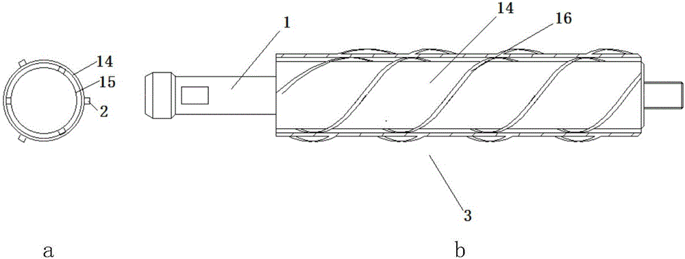
[0017] Such as figure 1 , figure 2 As shown, a gas well downhole cyclone atomization drainage gas production device includes a fishing head 1, the fishing head 1 is connected to the upper part of the flow bypass 3, the lower part of the flow bypass 3 is connected to the upper end of the flow guide tube 5, and the lower end of the flow guide tube 5 is connected to the upper end of the flow guide tube 5. The upper end of the cone 6 is threaded, and the outer wall of the lower end of the cone 6 is provided with a raised annular step; the elastic body 11 is sleeved on the outer wall of the cone 6 and connected by the shear pin 9. When the shear pin 9 is cut off, the elastic body 11 can Slide on the cone 6 outer walls; the elastic body 11 outer wall connection adopts an end of the spring pin 12 that steel wire is bent into;

[0018] refer t...


PUM


Abstract

Disclosed is a gas well underground rotational flow atomization water drainage and gas recovery device. A fishing head is connected to the upper portion of a spoiler, the lower portion of the spoiler is connected to the upper end of a flow guide barrel, the lower end of the flow guide barrel is in threaded connection with the upper end of a conical body, and a protruding annular step is arranged on the outer wall of the lower end of the conical body. The outer wall of the conical body is sleeved with an elastic body and connected with the elastic body through a shear pin, and the shear pin is shorn off so that the elastic body can slide on the outer wall of the conical body. The outer wall of the elastic body is connected with one end of a spring pin formed by bending a steel wire. The other end of the spring pin is connected with one end, namely a round end, of a spring, and the other end of the spring is in a bent hook shape. When underground gas-liquid two-phase fluid passes through an inner spoiler layer and an outer spoiler layer, the flow state of the fluid changes, the fluid rotates at high speed to generate shear force and centrifugal force, high-speed gas flow impacts, shears and abrades a low-speed liquid film, fog drops are obtained by damaging surface tension and viscous force of the liquid, and thus atomization is achieved. When the particle sizes of the liquid drops are smaller than a certain critical value, the accumulated liquid can be continuously discharged out of a shaft by means of energy of a gas well, and thus the recovery efficiency of the gas well is improved.

Description

technical field [0001] The invention relates to a downhole tool in the technical field of oil field gas recovery, in particular to a gas well downhole swirl atomization drainage gas recovery device. Background technique [0002] With the continuous deepening of gas field development, the problems of water production and liquid accumulation in gas wells have become increasingly prominent in the production process, and effective drainage and gas recovery technology has become the key to ensuring reasonable and efficient development of gas fields in the middle and late stages. The liquid carrying effect of the gas well is the best when the flow state of the wellbore is annular mist flow. In the middle and later stages of gas well production, the flow state of the wellbore is slug flow, stirring flow, and annular mist flow from bottom to top. The productivity of the gas well is poor and cannot reach When the liquid-carrying flow rate is critical, the bottom of the well begins to...

Claims


Application Information

Patent Timeline
IPC IPC(8): E21B43/12
CPCE21B43/121E21B43/122Y02P70/10
Inventor 徐建宁王怡
Owner 陕西圣润能源环保科技有限公司
Learn More