Quick heat exchange minitype thermal shock testing device

A technology of cold and heat shock and test device, which is applied in measurement devices, instruments, scientific instruments, etc., can solve problems such as uneven heating and cooling, and achieve the effect of accelerating heat exchange rate

Inactive Publication Date: 2017-03-22
成都尚智恒达科技有限公司
View PDF0 Cites 0 Cited by
  • Summary
  • Abstract
  • Description
  • Claims
  • Application Information

AI Technical Summary

Problems solved by technology

[0004] The invention provides a miniature thermal shock test device with rapid heat exchange to solve the problem of uneven heating and cooling in the electronic component test device in the prior art

Method used


Image

  • Quick heat exchange minitype thermal shock testing device
  • Quick heat exchange minitype thermal shock testing device
  • Quick heat exchange minitype thermal shock testing device

Examples


Embodiment 1

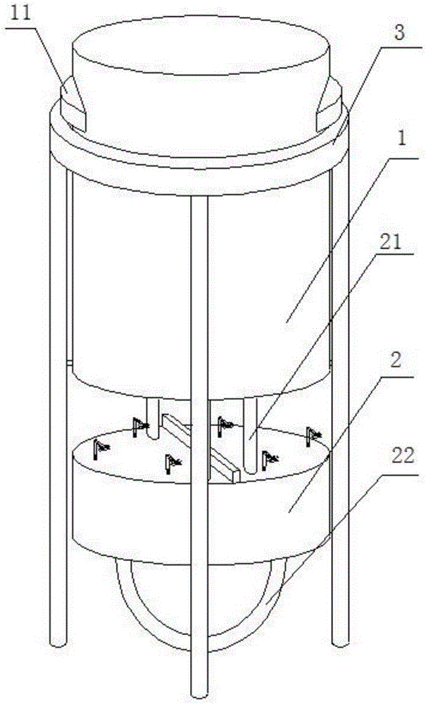
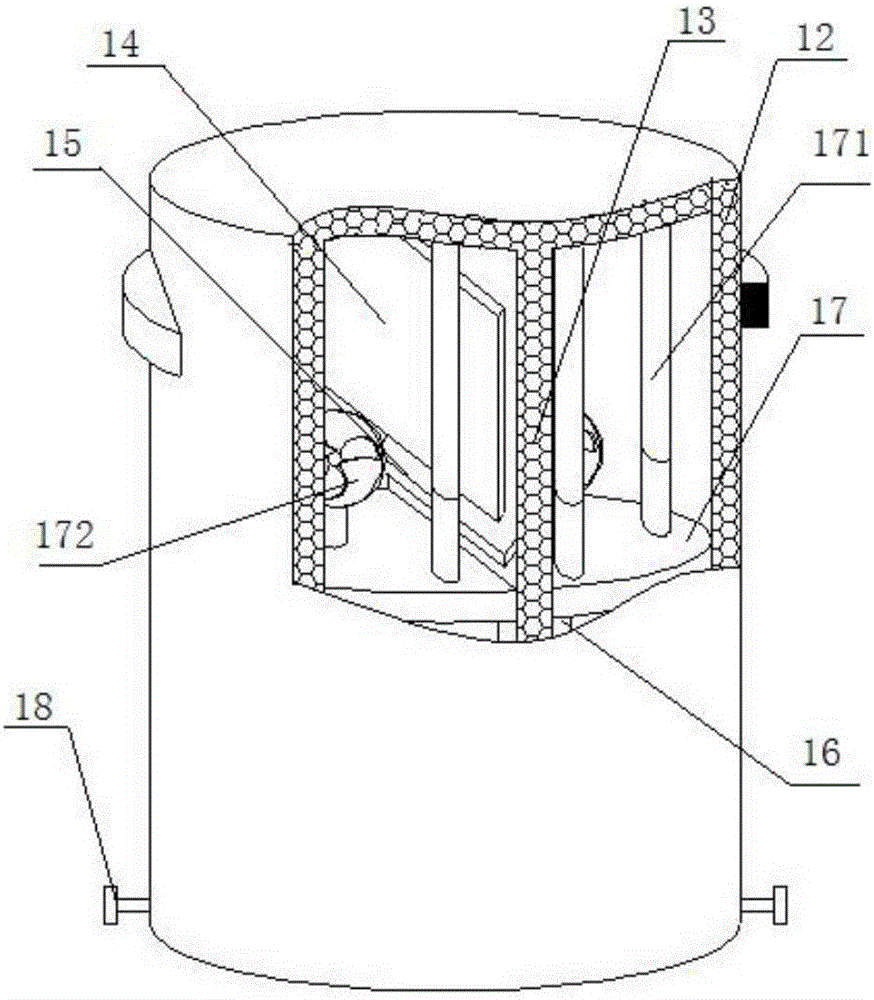
[0029] Such as figure 1 , figure 2 , Figure 4 , Figure 7 As shown, a miniature cold and thermal shock test device with rapid heat exchange includes a test body 1 and a test sample mounting base 2 that are socketed up and down. The test body 1 is covered with a bracket 3, and the test body 1 includes a thermal insulation shell 12 The thermal insulation shell 12 is cylindrical with an open lower end, and a thermal insulation partition 13 is arranged inside the thermal insulation casing 12. The thermal insulation partition 13 and the test sample installation base 2 separate the thermal insulation casing 12 into a cold test room and a cold test chamber independently arranged on the left and right sides. The thermal test room, the cold test room and the hot test room are respectively equipped with a refrigeration device and a heating device; the inner wall of the heat preservation shell 12 is provided with a limit block 15 and a sealing ring plate 16, and the inner wall of the...

Embodiment 2

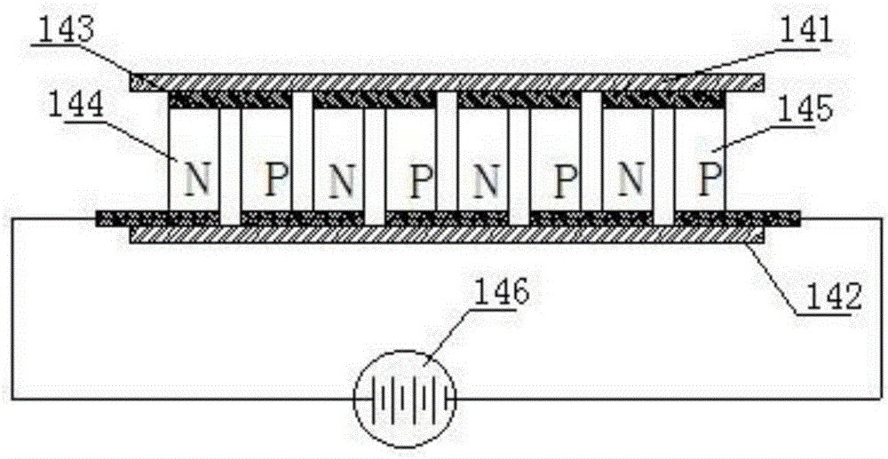
[0037] Such as image 3 As shown, further optimization is carried out on the basis of a rapid heat transfer miniature thermal shock test device described in Example 1. The upper half of the heat insulation partition 13 is inlaid with a semiconductor refrigeration device 14, and the semiconductor refrigeration The device 14 is located above the limit block 15. The semiconductor refrigeration device 14 is composed of a cold end face 141, a hot end face 142, a metal conductor 143, an N-type semiconductor 144, a P-type semiconductor 145 and a DC power supply 146. The cold end face 141 and the hot end face 142 The material is an insulating ceramic sheet. The N-type semiconductor 144 and the P-type semiconductor 145 are provided with several groups. 144 and the P-type semiconductor 145 are connected through a metal conductor 143, the metal conductor 143 is close to the inner side of the cold end surface 141 or the hot end surface 142, and the metal conductor 143, the N-type semicond...

Embodiment 3

[0042] Such as Figure 6 , Figure 8 As shown, further optimization is carried out on the basis of a rapid heat transfer miniature thermal shock test device described in Example 1. The test sample mounting base 2 is cylindrical, and the outer diameter of the test sample mounting base 2 is Equal to the inner diameter of the thermal insulation shell 12, at least 2 fixed mounts 23 are evenly distributed in the axial direction along the edge of the upper surface of the test sample mounting base 2, and the fixed mounts 23 include rotatably arranged on the upper surface of the test sample mounting base 2. A longitudinal support rod 231, the top of the longitudinal support rod 231 is rotatably connected with a horizontal telescopic rod 232, and the end of the horizontal telescopic rod 232 is provided with an upper splint 233 and a lower splint 234 arranged up and down, and the upper splint 233 and the lower splint Clamping screws 235 are provided between the splints 234 .

[0043] ...


PUM


Abstract

The invention discloses a quick heat exchange minitype thermal shock testing device, and relates to the field of electronic product testing, the testing device includes a test body and a test sample mounting base seat being connected in an upper and lower sleeve joint, the test body includes a thermal shell, the inside of the thermal shell is provided with a thermal partition board, the thermal partition board and the test sample mounting base seat partition the thermal shell into a cold laboratory and a thermal laboratory provided independently on the left side and the right side, the inner wall of the thermal shell is provided with a limit block and a sealing ring plate, the limit block is located below the semiconductor refrigerator, the thermal shell inside is provided with a movable sealing plate in a sleeved mode, the movable sealing plate is provided between the limit block and the sealing ring plate, the movable sealing plate is provided with a draught fan, the place between the upper surface of the movable sealing plate and the top part of the thermal shell is provided with a vertical guide pillar, the guide pillar is composed of an inner pipe of an inner pipe and an outer pipe connected in a sleeved mode and a protection casing, the inner pipe and the inside of the protection casing are provided respectively with an upper conductor and a lower conductor, the upper conductor and the lower conductor are respectively electrically connected with the draught fan, the bottom of the movable sealing plate is connected with the mounting base seat of the test sample.

Description

technical field [0001] The invention relates to the field of electronic product testing, in particular to a miniature thermal shock test device with rapid heat exchange. Background technique [0002] The hot and cold test chamber, also known as the "hot and cold shock test chamber", is a testing device that can instantly switch from high temperature to low temperature. It is used to test material structures or composite materials. To the extent that it can endure, the chemical changes or physical damage caused by thermal expansion and contraction of the sample can be detected in the shortest time. [0003] The existing cold and hot test chambers are bulky, require a large floor space, and are inconvenient to move; they are expensive and cost tens of thousands of yuan, which is difficult for small enterprises to bear; when the cold and hot test chambers are opened and closed, they exchange heat with the environment Many, which affect the energy utilization efficiency. After ...

Claims


Application Information

Patent Timeline
IPC IPC(8): G01N3/60G01N3/02
CPCG01N3/60G01N3/02
Inventor 任无史晓莉
Owner 成都尚智恒达科技有限公司
Why Eureka
Try Eureka