Clamp for acoustic emission testing of material corrosion property and using method thereof

A technology for acoustic emission detection and corrosion performance, which is applied in the direction of analyzing materials, weather resistance/light resistance/corrosion resistance, measuring devices, etc. and complex disassembly operations

Active Publication Date: 2017-03-22
TIANJIN UNIV
View PDF5 Cites 5 Cited by
  • Summary
  • Abstract
  • Description
  • Claims
  • Application Information

AI Technical Summary

Problems solved by technology

The main disadvantages of existing test devices that use both acoustic emission technology and electrochemical technology to detect material corrosion properties are: (1) The size of the tested sample required by the traditional test device is too large, and it is impossible to test tiny samples
Welded joints are usually the weakest link in structural parts. If you want to perform acoustic emission and electrochemical detection on different areas of welded joints (weld root, cover surface, weld center, high temperature and low temperature thermal influence, etc.), based on sampling (2) In order to facilitate the installation of the acoustic emission sensor, the sample to be tested usually needs to be installed at the bottom of the electrolytic cell as a working electrode, so the existing test device limits the ability of the corrosive medium Heating and heat preservation; (3) Acoustic emission testing and electrochemical testing that cannot simulate the corrosion performance of materials in a variety of mixed gas environments; (4) The operation of sample installation and removal is complicated

Method used


Image

  • Clamp for acoustic emission testing of material corrosion property and using method thereof
  • Clamp for acoustic emission testing of material corrosion property and using method thereof
  • Clamp for acoustic emission testing of material corrosion property and using method thereof

Examples


Embodiment Construction

[0086] The present invention will be further described below in conjunction with the accompanying drawings and embodiments, but it should not be construed as a limitation of the present invention.

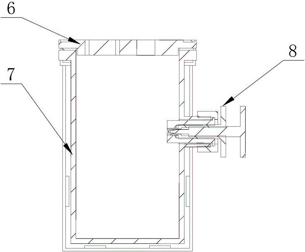
[0087] The sample fixture used for electrochemical corrosion test, that is, the above-mentioned attached Figure 8 The sample installation device in the test is composed of a stepped thread waveguide, a primary sleeve, a secondary sleeve, a tertiary sleeve and a sealing ring. A stepped thread waveguide, a primary sleeve, a secondary sleeve, and a tertiary sleeve The cylinder and the sealing ring are set coaxially, wherein: the stepped thread waveguide is provided with a first external thread and a second external thread, and the first external thread is connected with the internal thread of the first-stage sleeve, so that the front end of the stepped thread waveguide is placed In the first cavity and the second cavity of the first-level sleeve, the second external thread is placed ...


PUM

PropertyMeasurementUnit
diameteraaaaaaaaaa
lengthaaaaaaaaaa
diameteraaaaaaaaaa

Abstract

The invention discloses a clamp for acoustic emission testing of the material corrosion property and a using method thereof. The device is composed of a stepped thread waveguide rod, a primary sleeve, a secondary sleeve, a tertiary sleeve, a sealing ring and an acoustic emission sensor. A first external thread of the stepped thread waveguide rod is connected with an internal thread of the primary sleeve, a second external thread of the stepped thread waveguide rod is arranged on the outer side of a second cavity of the primary sleeve, a fixing end is arranged at the rear end of the stepped thread waveguide rod, and the acoustic emission sensor is arranged at the fixing end; an external thread of the primary sleeve is connected with an internal thread of the tertiary sleeve, so that the primary sleeve is arranged inside a third cavity and a fourth cavity of the tertiary sleeve; the tertiary sleeve is sleeved with the secondary sleeve, and the sealing ring is arranged between the tertiary sleeve and the secondary sleeve. A sample is installed in a thread-connection mode, corrosion acoustic emission and electric chemical signals are transmitted through the stepped thread waveguide rod, and compared with a traditional mode, the sample is more portable and more efficient to assemble, disassemble and clean.

Description

technical field [0001] The invention relates to the field of material corrosion performance testing, in particular to a fixture for acoustic emission detection of material corrosion performance and a use method thereof. Background technique [0002] Corrosion is a slow damage process of materials in harsh service environments, which has the characteristics of strong concealment, accidental, sudden and serious destructiveness. Electrochemistry is a commonly used test method for quickly evaluating the corrosion resistance of materials, such as potentiodynamic polarization, constant potential polarization, cyclic potentiodynamic polarization, and electrochemical impedance testing. Electrochemical technology is mainly aimed at the destructive detection of small samples, with the purpose of predicting or evaluating the corrosion resistance of materials in advance, but it cannot conduct online detection of the corrosion status of large-scale components in service. Acoustic emissi...

Claims


Application Information

Patent Timeline
Patent Type & Authority Applications(China)
IPC IPC(8): G01N17/04G01N17/02
CPCG01N17/02G01N17/04Y02E30/30
Inventor 徐连勇张志强韩永典荆洪阳赵雷
Owner TIANJIN UNIV
Why Eureka
Try Eureka