Display device and method for controlling same

A display device and display panel technology, which is applied to identification devices, measuring devices, static indicators, etc., can solve the problems of large thickness of the display panel, and achieve the effect of reducing the thickness

Active Publication Date: 2017-03-22
BOE TECH GRP CO LTD
View PDF6 Cites 27 Cited by
  • Summary
  • Abstract
  • Description
  • Claims
  • Application Information

AI Technical Summary

Problems solved by technology

[0005] In order to solve the problem of relatively large thickness of the display panel in the related art,

Method used


Image

  • Display device and method for controlling same
  • Display device and method for controlling same
  • Display device and method for controlling same

Examples


Example Embodiment

[0050] In order to make the objectives, technical solutions and advantages of the present invention clearer, the embodiments of the present invention will be further described in detail below with reference to the accompanying drawings.

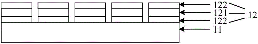
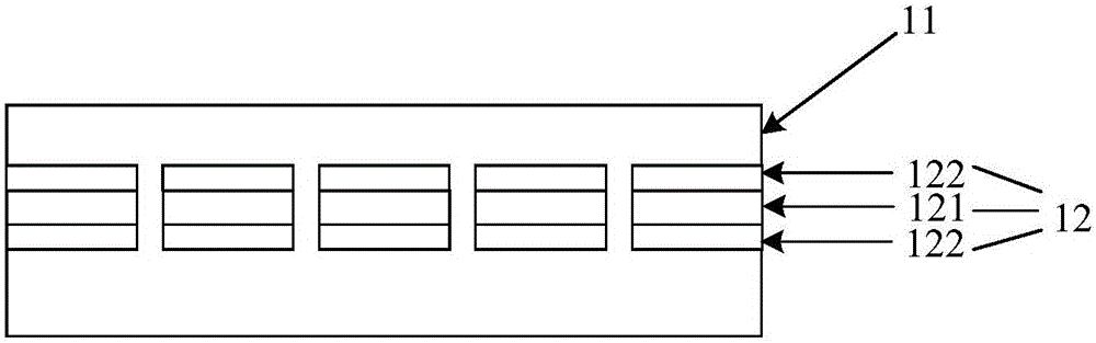
[0051] figure 1 It is a schematic structural diagram of a display device according to an embodiment of the present invention. The display device may include:

[0052] Display panel 11 and a plurality of ultrasonic components 12 arranged on the same layer.

[0053] Any ultrasonic component in the plurality of ultrasonic components 12 includes a piezoelectric layer 121 and two electrodes 122, and the two electrodes 122 are respectively disposed on both sides of the piezoelectric layer 121;

[0054]Wherein, any ultrasonic component 12 can be used for transmitting ultrasonic waves and receiving ultrasonic waves. Any ultrasonic component 12 can apply a voltage of a preset frequency to the piezoelectric layer 121 through the two electrodes 122 to...


PUM


Abstract

The invention discloses a display device and a method for controlling the same, and belongs to the field of display technologies. The display device comprises a display panel and a plurality of ultrasonic assemblies. The ultrasonic assemblies are arranged on the same layer; each ultrasonic assembly comprises a piezoelectric layer and two electrodes, and the two electrodes of each ultrasonic assembly are respectively arranged on two sides of the piezoelectric layer of the ultrasonic assembly. The display device is provided with the ultrasonic assemblies which are positioned on the same layer, ultrasonic waves can be transmitted and received by the ultrasonic assemblies without ultrasonic receiving assemblies or ultrasonic generating assemblies, accordingly, the problem of thick display panels in the prior art can be solved, and effects of reducing the thickness of the display panel can be realized.

Description

technical field [0001] The present invention relates to the field of display technology, and in particular, to a display device and a control method of the display device. Background technique [0002] At present, various electronic devices have a fingerprint recognition function. More and more people are accustomed to using the fingerprint recognition function to perform various operations, such as unlocking the screen and confirming payment. [0003] A display device with a fingerprint recognition function includes a display panel, a plurality of ultrasonic wave receiving components arranged in the display panel, and a plurality of ultrasonic wave generating components arranged outside the display panel. When fingerprint recognition is performed, the ultrasonic generating component emits ultrasonic waves, which are reflected after touching the finger, and the ultrasonic receiving component receives the reflected ultrasonic waves. For the difference in ultrasonic absorpti...

Claims


Application Information

Patent Timeline
IPC IPC(8): G09F9/00G09G3/20G09G3/3208H01L27/32G06K9/00
CPCG09F9/00G09G3/20G09G3/3208G06V40/1306H10K59/00G01S7/52079G01S15/8913G01S15/8925G01S7/52085
Inventor 赵利军
Owner BOE TECH GRP CO LTD
Why Eureka
Try Eureka