Power equipment

A technology of power equipment and cables, which is applied in the direction of power cables, circuits, floating cables, etc., can solve the problems that the installation parts are difficult to deal with, and achieve the effect of changing styles, compact structure, and improving durability

Active Publication Date: 2017-03-22
STATE GRID JIANGSU ELECTRIC POWER CO LTD SUQIAN POWER SUPPLY BRANCH +2
View PDF9 Cites 4 Cited by
  • Summary
  • Abstract
  • Description
  • Claims
  • Application Information

AI Technical Summary

Problems solved by technology

Such an installation environment is difficult to deal with with conventional installation parts

Method used


Image

  • Power equipment
  • Power equipment
  • Power equipment

Examples


Embodiment 1

[0035] An electric device includes a main body and an auxiliary structure.

[0036] The body includes a cable; the cable is a multi-layer structure, which sequentially includes a wire, an insulating film, a first filling layer, a first armor layer, a second filling layer, an insect-proof copper tape, and a third filling layer from the inside to the outside , second armor layer, anti-corrosion coating, and outer sheath layer.

[0037] The fillers in the first filling layer and the second filling layer are waterproof and hydrogen-absorbing polyalphaolefins, which have excellent waterproof and hydrogen-absorbing properties, and have multi-layer protection effects on cables.

[0038] The third filling layer is an air-filled hollow layer, and the air-filled hollow layer can adjust the density of the cable, such as making the density greater than, less than or equal to the liquid density in the environment, so that the cable can be better stabilized in the environment , or suspend....

Embodiment 2

[0048] This embodiment is realized on the basis of the foregoing embodiment 1, and mainly introduces the preparation and production method of the cable.

[0049] The preparation and production method of the cable comprises the following steps:

[0050] (1) Conductor stranding, use conductor stranding equipment to strand, obtain conductor cores, conductor cores are reeled by variable diameter cabling machine;

[0051] (2) Extrude, input the wire core on the cable forming machine to the three-layer co-extrusion equipment, wrap the insulating film, obtain the insulated wire core, and pack;

[0052] (3) Forming the first filling layer. A first filling material is coated on the surface of the insulated wire core to form a first filling layer.

[0053] (4) Assembling the first armor layer;

[0054] (5) Forming the second filling layer. A second filling material is coated on the surface of the first armor layer to form a second filling layer.

[0055] (6) Insect-proof copper tap...

Embodiment 3

[0063] This embodiment is realized on the basis of the foregoing embodiment 1 or 2, and mainly introduces auxiliary structures.

[0064] The auxiliary structure includes auxiliary structure 1; the function of auxiliary structure 1 is to fix and install the electric equipment, specifically a load-bearing structure compatible with cables and integrated pipes. In humid environments, such as lake bottoms, river bottoms, mud puddles, and seabeds, power cables can be arranged separately or integrated into special pipelines for unified arrangement.

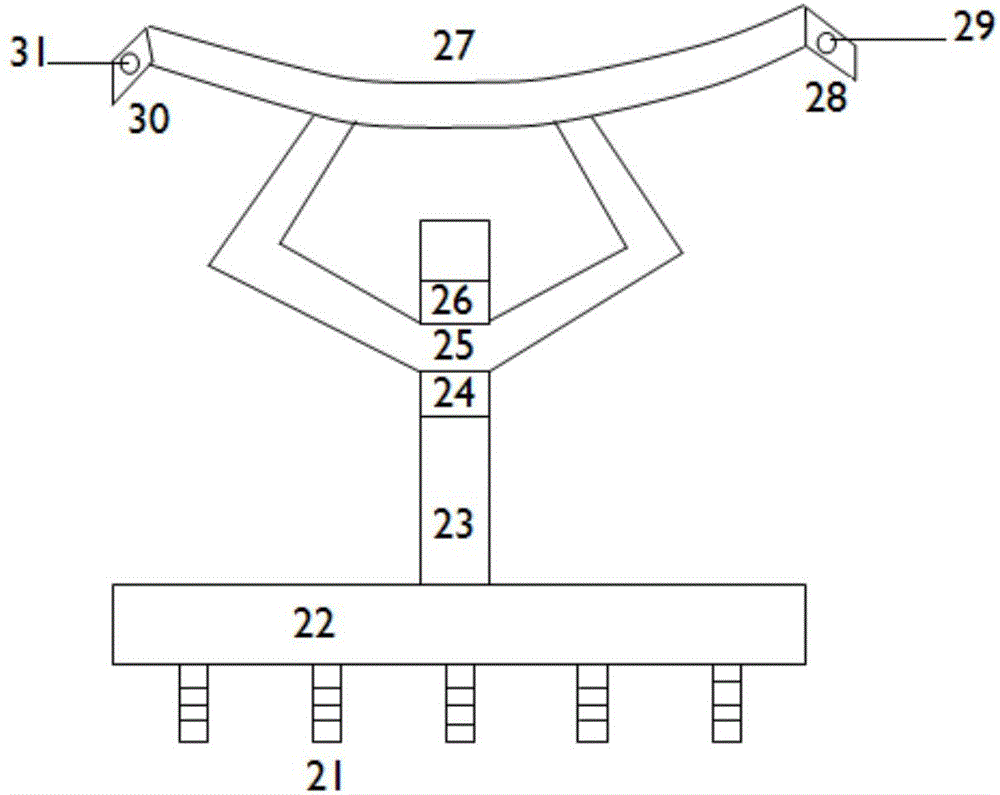
[0065] In order to facilitate the fixing of cables and their integrated pipes, a fixing seat was invented, such as image 3 As shown, the fixed seat includes a base (22), a first component and a second component.

[0066] like image 3 As shown, the bottom end of the base (22) is fixed on the support position such as the ground, the upper end of the base has a platform, and a stud (23) is vertically arranged above the platform, and the...


PUM


Abstract

The invention relates to power equipment, which comprises a body and an auxiliary structure, wherein the body comprises a cable; the cable is of a multi-layer structure and sequentially comprises a wire, an insulating film, a first filling layer, a first armor layer, a second filling layer, an insect-proof copper strip, a third filling layer, a second armor layer, an anticorrosive coating and an outer sheath layer from inside to outside; and the auxiliary structure at least comprises an auxiliary structure I and an auxiliary structure II. The power equipment is compact in structure, has the advantages of being solid, anticorrosive and durable, and has a wide market prospect.

Description

technical field [0001] The invention relates to power equipment, in particular to a power cable and its auxiliary structure, belonging to the field of power. Background technique [0002] At present, power equipment has been applied to various fields. Especially cables, signal lines, etc. have more and more uses, and their installation places are also getting wider and wider. The humid environment is a big killer for power equipment. It not only easily leads to corrosion and failure of the equipment due to the humid environment, but also causes special difficulties in the installation and fixing of the equipment, which is significantly different from installation in factories, homes and other conventional places. [0003] Hydrophobicity is a key factor for the long-term reliable operation of electrical equipment, especially cables. In addition to being eroded by liquid water and gaseous water, power equipment in a humid environment is also subject to the adhesion of organi...

Claims


Application Information

Patent Timeline
Patent Type & Authority Applications(China)
IPC IPC(8): H01B7/02H01B7/12H01B7/17H01B7/18H01B7/22H01B7/28H01B7/285H01B7/32H01B7/40H01B9/00H01B13/00
CPCH01B7/0275H01B7/12H01B7/17H01B7/1875H01B7/226H01B7/2806H01B7/285H01B7/32H01B7/40H01B9/00H01B13/00
Inventor 施永妹
Owner STATE GRID JIANGSU ELECTRIC POWER CO LTD SUQIAN POWER SUPPLY BRANCH
Why Eureka
Try Eureka