Nanogenerator

A technology of nano generators and friction generators, applied in the direction of friction generators, generators/motors, electrical components, etc., can solve the problems of limited storage capacity of external power supply, pollute the environment, etc., and achieve the effect of overcoming the limited storage capacity

Active Publication Date: 2017-03-22
BEIJING INST OF NANOENERGY & NANOSYST
View PDF4 Cites 5 Cited by
  • Summary
  • Abstract
  • Description
  • Claims
  • Application Information

AI Technical Summary

Problems solved by technology

[0003] The purpose of the present invention is to provide a nano generator to solve the problems of limited storage capacity and polluting environment of the existing external power supply in the prior art

Method used


Image

  • Nanogenerator
  • Nanogenerator
  • Nanogenerator

Examples


Embodiment approach

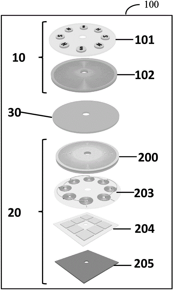
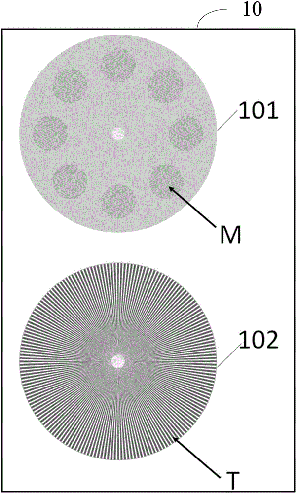
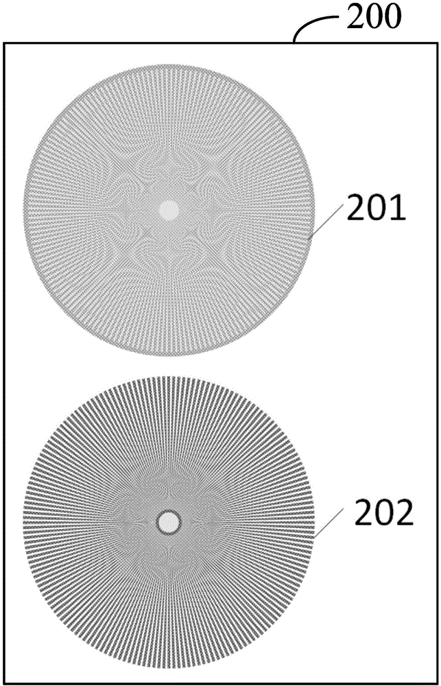
[0022] According to an embodiment of the present invention, the rotor 10 includes a magnet layer 101 and a friction unit layer 102 arranged coaxially and sequentially. The stator 20 includes an electrode unit layer 200, a coil layer 203, a thermoelectric sheet layer 204 and a thermally conductive metal plate 205 arranged coaxially in sequence, wherein the friction unit layer 102, the electrode unit layer 200 and the isolation layer 30 A friction generator is formed, the magnet layer 101 and the coil layer 203 form a magnetoelectric generator, and the thermoelectric sheet layer 204 and the heat conduction metal plate 205 form a thermoelectric generator.

[0023] Wherein, the isolation layer 30 is located between the friction unit layer 102 and the electrode unit layer 200 . The friction unit layer 102 does not need additionally attaching electrode layers and connecting wires, and can move freely.

[0024] combine Figure 1-5 As shown, the magnet layer 101 includes a first sub...


PUM


Abstract

The invention relates to the technical field of nano-energy generation, and discloses a nangenerator. The nangenerator comprises a rotor, a stator, and an isolation layer disposed between the rotor and the stator. One part of the rotor, a first part of the stator and the isolation layer form a friction generator. Moreover, the other part of the rotor and the second part of the stator form a magnetoelectric generator, and the third part of the stator form a thermoelectric generator. The nanogenerator achieves the stable DC current output through the coupling of a triboelectric effect, a magnetoelectric effect and a thermoelectric effect, can supply renewable electric energy to various types of electronic equipment, and solves problems that an existing external power supply is limited in storage capacity and causes environment pollution.

Description

technical field [0001] The invention relates to the technical field of micro-nano energy power generation, in particular to a nanometer generator. Background technique [0002] With the rapid development of mobile electronic devices, people rely more and more on those devices for communication, security and sensing. All of these devices currently require an external power source, such as a lithium battery, which has a limited energy storage capacity and has environmental pollution problems. Correspondingly, the use of lithium batteries cannot meet the high power demand in remote areas or specific environments. For example, when scientists or explorers in developing countries or regions cannot meet the needs of traditional electric energy during the expedition, it is crucial to develop renewable mobile energy driven by human motion. There is therefore a need for a device that can use human motion to power electronic devices. Contents of the invention [0003] The purpose...

Claims


Application Information

Patent Timeline
Patent Type & Authority Applications(China)
IPC IPC(8): H02N1/04H02K35/02H02N11/00
Inventor 杨亚王雪王中林
Owner BEIJING INST OF NANOENERGY & NANOSYST
Why Eureka
Try Eureka