Method for controlling rotating speed synchronization of dual-permanent magnet synchronous motor drive system

A technology of permanent magnet synchronous motor and synchronous motor, which is applied in multiple motor speed/torque control, motor generator control, AC motor control, etc. It can solve the problem of weak system robustness, difficulty in establishing mathematical models, PMSM Variables and other issues, to achieve the effect of improving tracking performance and robust performance, not requiring high model accuracy, and enhancing the coupling effect of rotational speed

Inactive Publication Date: 2017-03-22
TIANJIN POLYTECHNIC UNIV
View PDF5 Cites 23 Cited by
  • Summary
  • Abstract
  • Description
  • Claims
  • Application Information

AI Technical Summary

Problems solved by technology

The traditional control method is simple in structure, easy to adjust, and the synchronization performance of the system in the start-stop phase is good, but there are the following problems: (1) PMSM has the characteristics of multi-variable, nonlinear, strong coupling, etc., and it is difficult to establish its accurate Mathematical model, which makes the use of PI control vulnerable to factors such as system internal parameter changes and external disturbances, and the system robustness is not strong
(2) When one of the motors is disturbed by the load and the speed changes, because there is no coupling between the two motors, it cannot be "sensed" by the other motor, so a speed synchronization error will occur between the two motors Desynchronization phenomenon, poor synchronization performance of the system
(3) When there is a synchronization error in the speed of the two motors, they can only be adjusted through their respective speed loops and current loops, and the adjustment speed is slow

Method used


Image

  • Method for controlling rotating speed synchronization of dual-permanent magnet synchronous motor drive system
  • Method for controlling rotating speed synchronization of dual-permanent magnet synchronous motor drive system
  • Method for controlling rotating speed synchronization of dual-permanent magnet synchronous motor drive system

Examples


Embodiment Construction

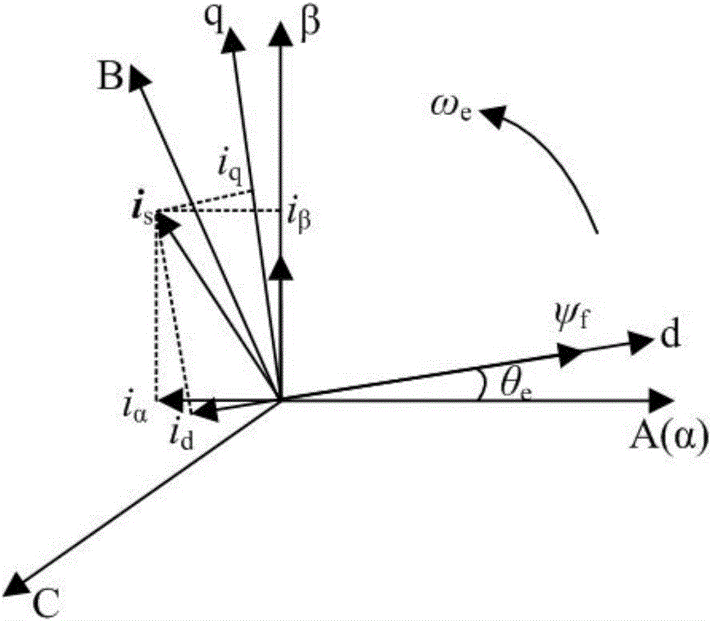
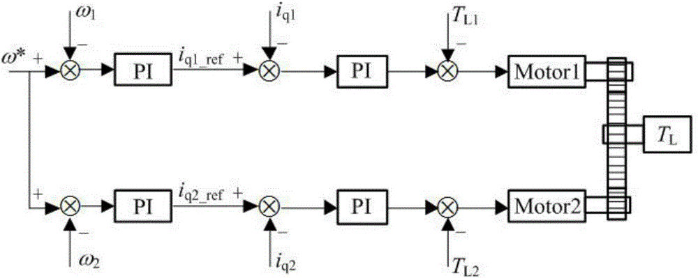
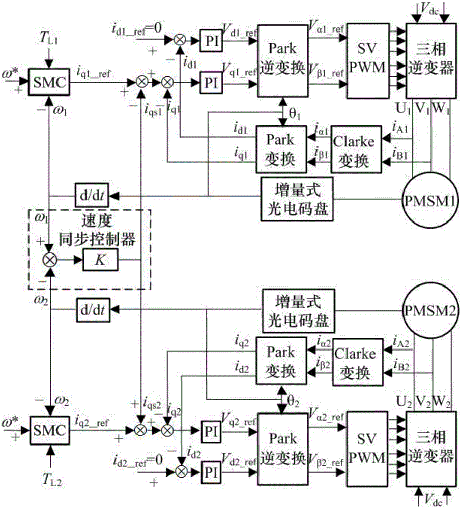
[0042]In order to enhance the robustness of the entire system to load disturbances, the dual permanent magnet synchronous motor drive system speed synchronization control method proposed by the present invention firstly designs an integral sliding mode speed controller based on the principle of sliding mode control to improve the speed of a single motor. For the robustness of load disturbance, based on the principle of cross-coupling, a speed synchronous controller is designed to compensate the current loops of the two motors. By selecting the appropriate feedback synchronization coefficient, the speed of the two motors can be as fast as possible when they are disturbed by the load. Synchronization can be achieved in a timely manner, thereby improving the synchronization of the entire system under load disturbance and the rapidity of speed recovery. The present invention will be further described below from the aspects of the permanent magnet synchronous motor mathematical mode...


PUM


Abstract

The present invention discloses a method for controlling rotating speed synchronization of a dual-permanent magnet synchronous motor drive system. The method comprises the steps of establishing a discrete mathematical model of a permanent magnet synchronous motor, wherein the discrete mathematical model comprises a voltage equation and an electromagnetic torque equation of the permanent magnet synchronous motor in a d-q axis coordinate system, and a motion equation of the permanent magnet synchronous motor; according to a slide mode control principle, designing rotating speed ring controllers of two permanent magnet synchronous motors into integral slide mode speed controllers; and according to a cross coupling principle, designing a speed synchronous controller, and compensating current rings of the two permanent magnet synchronous motors. The system has good robustness and is rapid when load disturbance occurs, and the rotating speed tracking and synchronization performance of the dual-motor drive system are effectively improved.

Description

technical field [0001] The invention relates to the field of multi-motor speed coordinated control, and more specifically relates to a method for synchronously controlling the rotational speed of a double permanent magnet synchronous motor drive system. Background technique [0002] In large-scale CNC turntables, radar antennas, gantry cranes and other high-power and high-torque load occasions, in order to reduce the size of the motor, reduce the cost, and meet the demand for output power, two motors or multiple motors are often used to jointly drive the load. , and the speed synchronization performance among multiple motors will directly affect the reliability and control accuracy of the system. AC motors used in electrical transmission systems mainly include asynchronous motors and permanent magnet synchronous motors, and permanent magnet synchronous motors (Permanentmagnet synchronous motor, PMSM) are characterized by their small size, light weight, high power density, go...

Claims


Application Information

Patent Timeline
Patent Type & Authority Applications(China)
IPC IPC(8): H02P21/00H02P21/22H02P21/14H02P27/12H02P6/04
CPCH02P6/04H02P21/0007H02P21/14H02P27/12
Inventor 夏长亮李莉王志强谷鑫
Owner TIANJIN POLYTECHNIC UNIV
Why Eureka
Try Eureka