Synchronous scanning imaging system

An imaging system and synchronous scanning technology, which is applied to the components of the TV system, image communication, TV, etc., can solve the problems of difficult to guarantee stability, high precision requirements of driving machinery, and slow imaging speed, etc., to achieve fast scanning imaging, The effect of reducing the volume of the backscattering area and improving the image quality

Active Publication Date: 2017-03-22
GUILIN UNIV OF ELECTRONIC TECH
View PDF5 Cites 25 Cited by
  • Summary
  • Abstract
  • Description
  • Claims
  • Application Information

AI Technical Summary

Problems solved by technology

In the past, a single photodetection device such as a photomultiplier tube was used to perform two-dimensional scanning drive, or a linear array CCD was sca...

Method used


Image

  • Synchronous scanning imaging system
  • Synchronous scanning imaging system
  • Synchronous scanning imaging system

Examples


Embodiment Construction

[0024] In order to understand the above-mentioned purpose, features and advantages of the present invention more clearly, the present invention will be further described in detail below in conjunction with the accompanying drawings and specific embodiments. It should be noted that, in the case of no conflict, the embodiments of the present application and the features in the embodiments can be combined with each other.

[0025] In the following description, many specific details are set forth in order to fully understand the present invention. However, the present invention can also be implemented in other ways than described here. Therefore, the protection scope of the present invention is not limited by the specific implementation disclosed below. Example limitations.

[0026] Refer below Figure 1 to Figure 8 for further description.

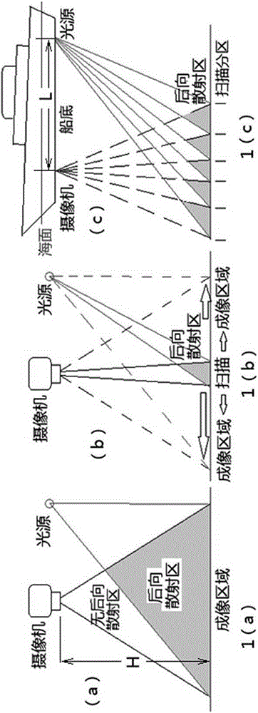
[0027] Such as figure 1 As shown in 1(c), a synchronous scanning imaging system includes an illumination device with a light source and a...


PUM


Abstract

The invention provides a synchronous scanning imaging system, used for imaging under the condition of artificial illumination. The synchronous scanning imaging system comprises an illumination device and an imaging device with a CMOS image sensor. The illumination device and the imaging device with a CMOS image sensor are located on the same side of the scanning imaging target, and the distance between the imaging device and the illumination device is greater than 1 / 2 of the preset furthest imaging distance. The synchronous scanning imaging system is characterized in that the imaging device uses the CMOS image sensor to roll the exposure electronic shutter, and the illumination device is controlled to emit a linear or narrow band illumination beam to scan the imaging target region, which is synchronous with the rolling exposure of the imaging device. By means of the synchronous scanning imaging system provided by the invention, the volume of the backscattered light area of the illuminating light is reduced, and the convenient and fast synchronous scanning controlling is realized.

Description

technical field [0001] The invention relates to the technical field of imaging equipment, in particular to a synchronous scanning imaging system. Background technique [0002] In environments with strong light scattering such as underwater, heavy fog, or at night, the image quality is seriously affected when the camera collects images with a large amount of scattered light entering the camera lens. This is because the scattered light is divided into forward scattering and back scattering. The forward reflection is the scattering along the direction of light propagation, and the back reflection is the scattering in the opposite direction to the incident light. Artificial lighting is usually used to take pictures at night or in deep water Or video, because the general light source and the camera are on the same side under artificial lighting conditions, the illumination light itself is much stronger than the diffuse reflection light of the imaging target, and the illumination ...

Claims


Application Information

Patent Timeline
IPC IPC(8): H04N5/225H04N5/235
CPCH04N23/56H04N23/55H04N23/54H04N23/70
Inventor 何志毅王敦东宋浠瑜陈博雯何宁陈名松
Owner GUILIN UNIV OF ELECTRONIC TECH
Why Eureka
Try Eureka