fuel pump controls

A technology for control devices and fuel pumps, applied to liquid fuel feeders, charging systems, combustion engines, etc., to achieve the effect of reducing operating noise

Inactive Publication Date: 2019-11-26
MIKUNI CORP
View PDF12 Cites 0 Cited by
  • Summary
  • Abstract
  • Description
  • Claims
  • Application Information

AI Technical Summary

Problems solved by technology

Therefore, there is room for improvement in terms of noise in the past plunger fuel pumps

Method used


Image

  • fuel pump controls
  • fuel pump controls
  • fuel pump controls

Examples


Embodiment Construction

[0035] An embodiment in which the present invention is embodied as a control device for a fuel pump for an engine mounted on a two-wheeled vehicle will be described below.

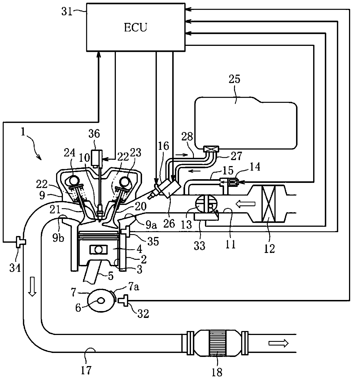
[0036] figure 1 It is a system configuration diagram showing a fuel pump control device according to the present embodiment.

[0037] The engine 1 of the present embodiment is configured as a four-stroke single-cylinder gasoline engine with a displacement of 50 cc, and is mounted on a two-wheeled vehicle as a driving power source. However, the specifications of the engine 1 are not limited thereto, and may be changed arbitrarily. However, the specifications of the engine 1 are not limited thereto, and may be changed arbitrarily.

[0038]A piston 4 is slidably disposed in a cylinder 3 formed on a cylinder block 2 of the engine 1 . The piston 4 is connected to a crankshaft 6 via a connecting rod 5 . The crankshaft 6 rotates in conjunction with the reciprocating motion of the piston 4 . A flywheel 7 is att...


PUM


Abstract

 This fuel pump control device is configured in such a manner that a plunger-type fuel pump 26 is activated using a DC motor 42 as a driving source, and fuel having been pressurized to a predetermined pressure is supplied to the injectors 16 of an engine 1. In addition to pre-setting the target duty ratio for driving current to be supplied to the DC motor 42 for each operating range of the engine 1, the target duty ratio for the idling range in particular is set to a lower value than that of other operating ranges to reduce noise, and these target duty ratios are stored in an ECU 31. While the engine 1 is operating, the drive current supplied to the DC motor 42 is controlled on the basis of the target duty ratio corresponding to the operating range at the that time, the fuel pump 26 is activated, and in the idling range, the operating speed of the fuel pump 26 is suppressed on the basis of the target duty ratio to reduce noise, thereby reducing operating noise.

Description

technical field [0001] The present invention relates to a control device of a fuel pump, in particular to a control device of a plunger-type fuel pump. The plunger-type fuel pump uses a motor as a driving source to reciprocate the plunger to pump fuel pressurized to a specified pressure. Injectors supplied to the engine. Background technique [0002] In the past, for the purpose of improving exhaust characteristics and reducing fuel consumption, fuel injection devices that electronically control the fuel supply to engines have been popularized, not only for four-wheeled vehicles, but also for various two-wheeled vehicles and generators. The structure of this fuel injection device is as follows. The fuel pump is used to draw the fuel in the fuel tank and pressurize it to a specified pressure. The injector is controlled on and off in a cycle-synchronous manner, and fuel is injected into the intake pipe. [0003] As such a fuel pump, a friction type fuel pump that pressurizes...

Claims


Application Information

Patent Timeline
Patent Type & Authority Patents(China)
IPC IPC(8): F02M37/08
CPCF02M37/08Y02T10/12
Inventor 菊池由祐马场悠一高桥晃
Owner MIKUNI CORP
Why Eureka
Try Eureka