Tripod type constant-velocity joint and image-forming device

A coupling and constant-velocity technology, which is applied in the field of speed couplings and image forming devices, can solve the problems of constant-speed rotation of photosensitive drums, tilting of photosensitive drums, assembly errors, etc., to achieve improved degrees of freedom, superior durability, and realization The effect of miniaturization

Active Publication Date: 2010-02-03
NTN CORP
View PDF8 Cites 0 Cited by
  • Summary
  • Abstract
  • Description
  • Claims
  • Application Information

AI Technical Summary

Problems solved by technology

[0010] In addition, when used in food manufacturing machines, oil and fat leaks to contaminate food. Therefore, it is necessary to take measures to prevent leakage by attaching a protective cover, etc., and the number of parts increases, the cost increases, and the constant velocity coupling becomes large. unfavorable situation
[0011] On the other hand, in the image forming apparatus described in Patent Document 2, the universal joint is a non-constant speed type universal joint, so the photosensitive drum cannot be rotated at a constant speed, even if the exposure position and the transfer position of the photosensitive drum are set to 180°, there is also an error during assembly or a tilt of the photosensitive drum, a deviation on 180° due to deflection, etc., so that the expansion and contraction of the image cannot be completely offset, and a high-quality image cannot be formed

Method used


Image

  • Tripod type constant-velocity joint and image-forming device
  • Tripod type constant-velocity joint and image-forming device
  • Tripod type constant-velocity joint and image-forming device

Examples


Embodiment Construction

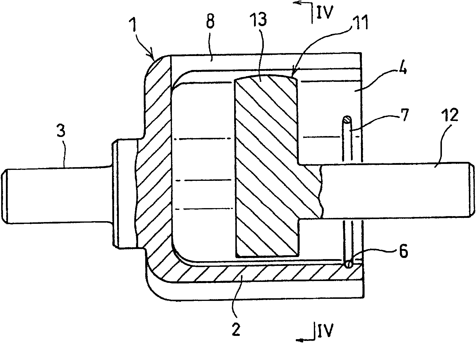
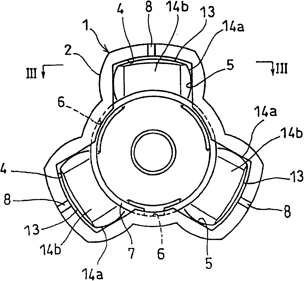
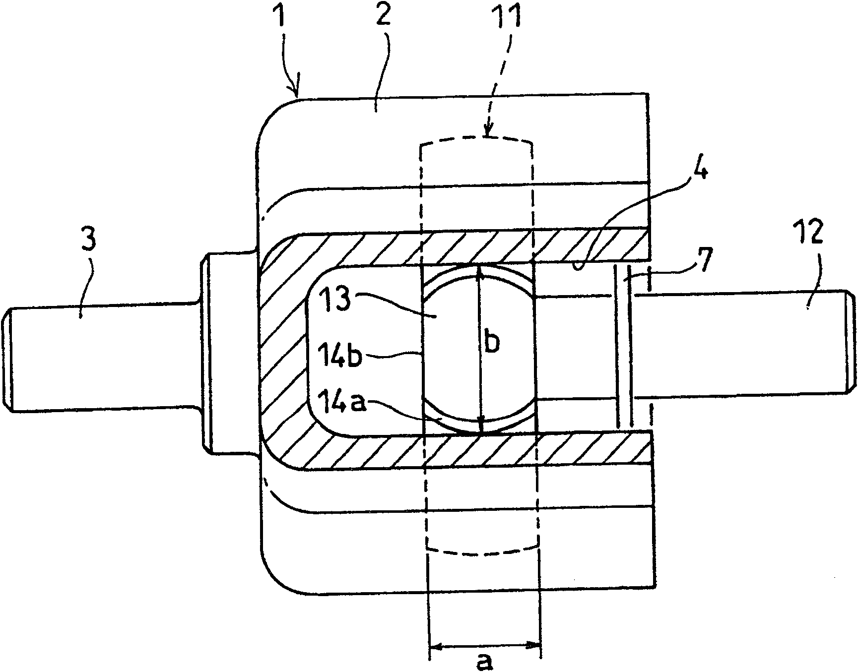
[0036] Embodiments of the present invention will be described below with reference to the drawings. Such as Figure 1 to Figure 4 As shown, the tripod constant velocity coupling is composed of an outer ring 1 and a tripod part 11 assembled inside it.

[0037] The outer ring 1 is configured such that a first shaft 3 is provided at the closed end of a cup-shaped portion 2 that is open at one end, and on the inner circumference of the cup-shaped portion 2 , there are formed shafts extending from the open end at intervals of 120° in the circumferential direction. Three track grooves 4 extending in the axial direction. A pair of side surfaces 5 opposing in the circumferential direction of the track groove 4 are flat surfaces parallel to each other.

[0038] The tripod member 11 has a second shaft 12 . Three protrusions 13 inserted into the respective track grooves 4 of the outer ring 1 are integrally provided on the tripod member 11 .

[0039] Each protruding portion 13 is free...


PUM


Abstract

A tripod type constant-velocity joint includes an outer ring formed with three axially extending track grooves circumferentially spaced apart from each other by 120 degrees. Each track groove has a pair of opposed, axially extending side faces. A tripod member is inserted in the outer ring. The tripod member includes three protrusions each slidably received in one of the track grooves and having apair of circumferentially curved side faces each opposing one of the pair of side faces of each track groove. Torque is thus transmitted between the outer ring and the tripod member. At least the protrusions of the tripod member are formed of a synthetic resin.

Description

technical field [0001] The present invention relates to a tripod constant velocity coupling which connects two shafts of a driving shaft and a driven shaft to transmit power of the driving shaft to the driven shaft, and an image forming apparatus using the tripod constant velocity coupling. Background technique [0002] Conventionally, a constant velocity coupling is known as a member for transmitting rotational torque of a drive shaft of an automobile to an axle. [0003] The above-mentioned constant velocity coupling is a component that maintains the constant velocity of the drive shaft and the driven shaft and allows angular displacement of the two shafts. Therefore, it is often used in various industrial machines other than automobiles. [0004] Among constant velocity couplings, there are fixed type constant velocity couplings that allow only angular displacement, and sliding type constant velocity couplings that allow angular displacement and shaft direction displaceme...

Claims


Application Information

Patent Timeline
Patent Type & Authority Patents(China)
IPC IPC(8): F16D3/20G03G15/00G03G21/16
Inventor 山崎雅之福泽觉大桥正明小林繁夫
Owner NTN CORP
Why Eureka
Try Eureka