
Limiting oscillation circuit

An oscillating circuit and amplitude limiting technology, applied in the field of information, can solve the problems affecting frequency stability, asymmetry, and large noise in the control loop, and achieve the effects of improving performance, good stability, and expanding the adjustable range.

Active Publication Date: 2017-03-22
SHENZHEN GOODIX TECH CO LTD
View PDF8 Cites 4 Cited by
  • Summary
  • Abstract
  • Description
  • Claims
  • Application Information

AI Technical Summary

Problems solved by technology

[0002] If the common LC oscillating circuit has no amplitude limit, the amplitude of the oscillating circuit will eventually stabilize to the power supply voltage. Such an oscillating circuit has the following disadvantages: 1. The oscillation waveform of the oscillating circuit is distorted, and its rising and falling edges are asymmetrical. making the 1 / f of the oscillator circuit 3 The inflection point of the noise moves to high frequency, which leads to the deterioration of its low-frequency phase noise; 2. The large oscillation amplitude causes the current flowing through the inductor to be very large, which makes the magnetic core of the inductor saturated, resulting in a change in the inductance value, which ultimately affects the stability of the frequency
[0003] The usual way to limit the amplitude is to use the amplitude or peak detection circuit to detect the oscillation amplitude, and then output a control voltage to control the bias current of the oscillation circuit, so as to achieve the effect of limiting the amplitude of the oscillation circuit, but this method also has the following disadvantages: 1. . The loop gain of this method is relatively large, which can easily lead to instability of the control loop; 2. The control loop itself will introduce relatively large noise, which will cause the phase noise of the oscillation circuit to deteriorate; 3. Most of the amplitude detection The circuit cannot accurately control the oscillation amplitude, which limits its practicality

Method used


Image

  • Limiting oscillation circuit
  • Limiting oscillation circuit
  • Limiting oscillation circuit

Examples


Embodiment Construction

[0047] The following will clearly and completely describe the technical solutions in the embodiments of the present invention with reference to the drawings in the embodiments of the present invention. Obviously, the described embodiments are part of the embodiments of the present invention, not all of them. Based on the embodiments of the present invention, all other embodiments obtained by persons of ordinary skill in the art without creative efforts shall fall within the protection scope of the present invention.

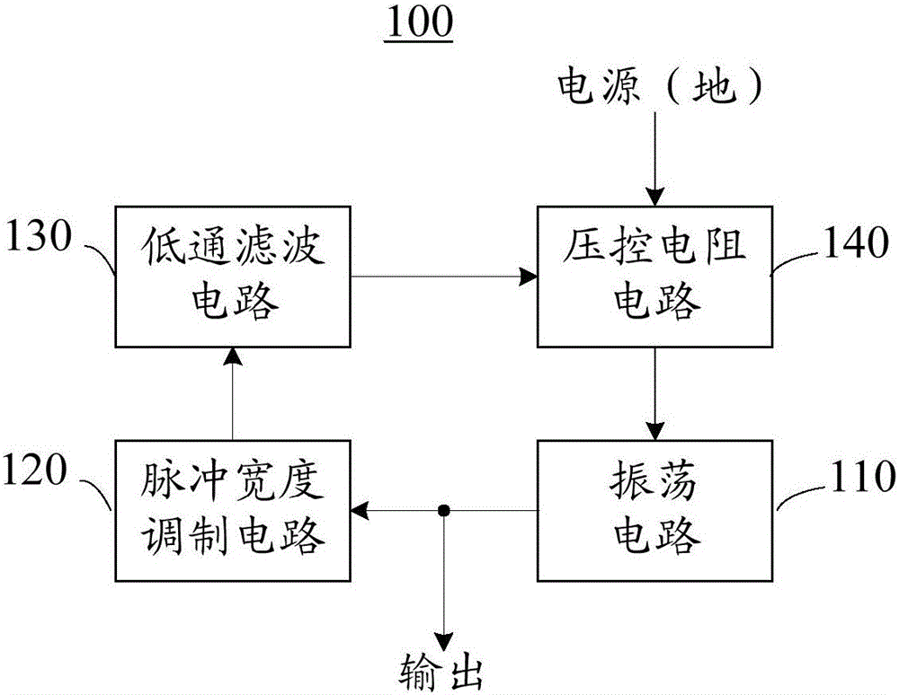
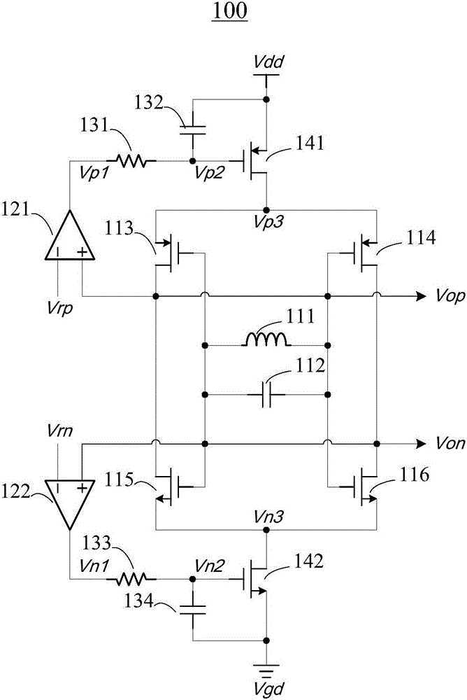
[0048] figure 1 A schematic diagram of a limiting oscillator circuit 100 according to an embodiment of the present invention is shown.

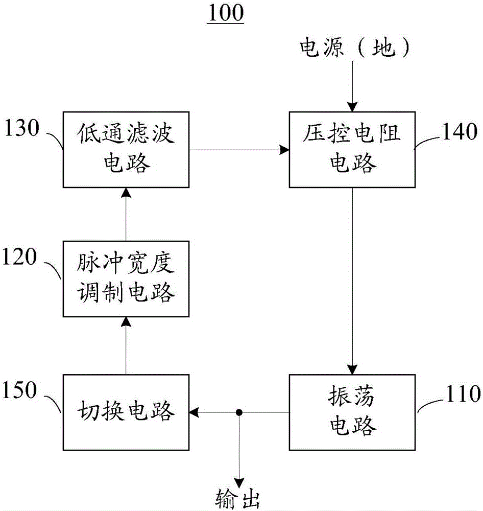
[0049] Such as figure 1 As shown, the limiting oscillator circuit 100 may include an oscillator circuit 110 , a pulse width modulation circuit 120 , a low-pass filter circuit 130 and a voltage-controlled resistor circuit 140 .

[0050] The oscillation circuit 110 is used for generating an oscillation signal.

[0051] The osci...


PUM


Abstract

The present invention discloses a limiting oscillation circuit. (110) for generating an oscillation signal; a pulse width modulation circuit (120) for generating a pulse width modulation signal based on the amplitude of the oscillation signal; a low pass filter circuit (130) for generating a pulse width modulation signal, (140) for controlling the voltage-controlled resistance circuit (140) for controlling the voltage-controlled voltage signal based on the control of the DC-controlled voltage signal, and a voltage-controlled voltage signal (140) for controlling the voltage- The resistance value of the voltage-controlled resistance circuit (140) is changed to control the amplitude of the oscillation signal. The limiting oscillation circuit of the embodiment of the present invention can improve the performance of the limiter oscillation circuit.

Description

technical field [0001] The present invention relates to the field of information technology, and more specifically, to a limiter oscillation circuit. Background technique [0002] If the common LC oscillating circuit has no amplitude limit, the amplitude of the oscillating circuit will eventually stabilize to the power supply voltage. Such an oscillating circuit has the following disadvantages: 1. The oscillation waveform of the oscillating circuit is distorted, and its rising and falling edges are asymmetrical. making the 1 / f of the oscillator circuit 3 The inflection point of the noise moves to high frequency, which leads to the deterioration of its low-frequency phase noise; 2. The large oscillation amplitude causes the current flowing through the inductor to be very large, which makes the magnetic core of the inductor saturated, resulting in a change in the inductance value, which ultimately affects the stability of the frequency . [0003] The usual way to limit the a...

Claims


Application Information

Patent Timeline
IPC IPC(8): H03B5/12H03B5/24H03B5/36
CPCH03B5/1206H03B5/24H03B5/364H03B5/1215H03B5/1228H03B5/1234H03B2200/009H03B5/32H03K4/48H03K7/08H03G3/001H03L5/00
Inventor 张孟文
Owner SHENZHEN GOODIX TECH CO LTD
Learn More