Laser bright flashlight

A laser and strong light technology, applied in the field of opto-mechanical, can solve the problems of inconvenient police execution and time delay, and achieve the effect of convenient and rapid switching between laser and white light, long service life and light weight

Pending Publication Date: 2017-03-29
HARGLO APPLIED LASER TECH INST CO LTD
View PDF8 Cites 6 Cited by
  • Summary
  • Abstract
  • Description
  • Claims
  • Application Information

AI Technical Summary

Problems solved by technology

The existing laser dazzler and LED flashlight are two independent devices, and police officers need to carry them at the same time when they go out to the police. Delay time and give suspects a chance to escape

Method used


Image

  • Laser bright flashlight
  • Laser bright flashlight
  • Laser bright flashlight

Examples


Embodiment 1

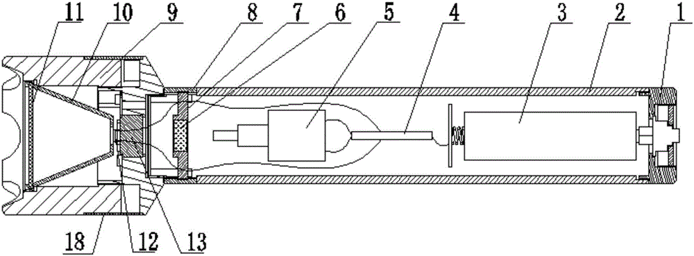
[0040] Such as Figure 1~4 As shown, a laser glare flashlight includes a sleeve 2, a battery 3, a circuit board 4, a laser 5, a focusing mechanism and a lamp cap 9, and the battery 3 and the laser 5 are all arranged in the sleeve 2, and the sleeve 2 The rear end is detachably provided with a back cover 1, and the battery 3 can be put into the sleeve 2, the battery 3 is a high-capacity battery, and the battery 3 is located near the back cover 1.

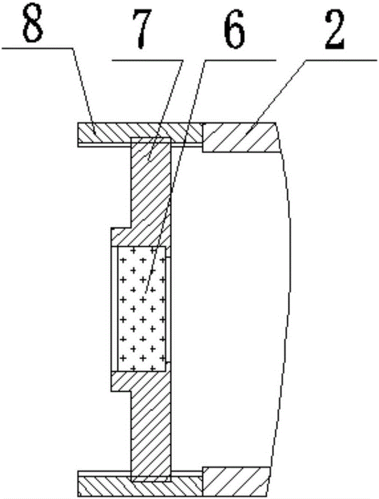
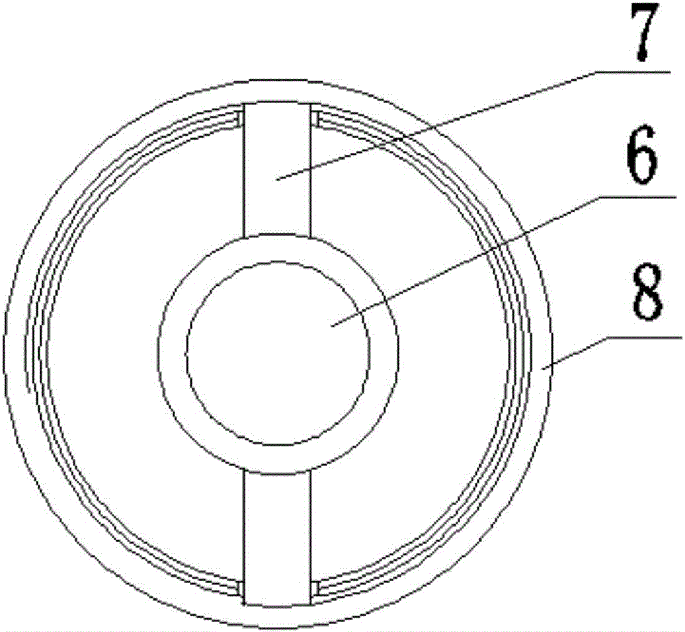
[0041] The lamp cap 9 is arranged on the front end of the sleeve 2, the focusing mechanism is arranged between the laser 5 and the lamp cap 9, the circuit board 4 is arranged between the laser 5 and the battery 3, and the circuit board 4 can control the continuous or pulse output of the laser, and can Control the LED lamp 12 to emit light sources with different brightnesses such as strong light and weak light.

[0042] The lamp holder 9 includes an LED lamp 12, a light source switching mechanism, a reflector 10 and a window mirror 11...

Embodiment 2

[0051] Such as Figure 5 As shown, a laser glare flashlight includes a sleeve 2, a battery 3, a circuit board 4, a laser 5, a focusing mechanism and a lamp cap 9, and the battery 3 and the laser 5 are all arranged in the sleeve 2, and the sleeve 2 There is a rear cover 1 at the rear end of the laser, the lamp holder 9 is arranged at the front end of the sleeve 2, the focusing mechanism is arranged between the laser 5 and the lamp holder 9, the battery 3 is arranged near the rear cover 1, and the lamp holder 9 is provided with an LED light 12. The reflective cup 10 and the window mirror 11 , the circuit board 4 is electrically connected between the LED lamp 12 , the laser 5 and the battery 3 .

[0052] The LED lamps 12 are provided in multiples and arranged uniformly, and the laser outlet 20 is located at the center of the uniformly distributed LED lamps 12 . A plurality of LED lamps 12 can share one reflective cup 10 .

Embodiment 3

[0054] Such as Figure 6 As shown, a laser glare flashlight includes a sleeve 2, a battery 3, a circuit board 4, a laser 5, a focusing mechanism and a lamp cap 9, and the battery 3 and the laser 5 are all arranged in the sleeve 2, and the sleeve 2 There is a rear cover 1 at the rear end of the laser, the lamp holder 9 is arranged at the front end of the sleeve 2, the focusing mechanism is arranged between the laser 5 and the lamp holder 9, the battery 3 is arranged near the rear cover 1, and the lamp holder 9 is provided with an LED light 12. The reflective cup 10 and the window mirror 11 , the circuit board 4 is electrically connected between the LED lamp 12 , the laser 5 and the battery 3 .

[0055] The LED lamps 12 are provided in multiples and arranged uniformly, and the laser outlet 20 is located at the center of the uniformly distributed LED lamps 12 . Each LED lamp 12 uses a reflective cup 10 respectively.


PUM


Abstract

The invention discloses a laser bright flashlight. The laser bright flashlight comprises a rear cover, a sleeve, a battery, a circuit board, a laser, a focus lens, a focusing rack, a focusing ring, a lamp holder, a heat sink, LEDs, reflective cups, a window mirror and the like, wherein the battery is a high-capacity battery; the circuit board has the function of controlling the laser and the LEDs; the laser can emit continuous and pulse laser; the LEDs can emit white light with different brightness; the spot size of laser can be adjusted; the white light emitted by the LEDs is sent out after being collimated by the reflective cups; and laser and the LED light source can be sent out from the end surface or the side surface respectively. The laser bright flashlight realizes integration of laser equipment and white-light illuminating equipment, is convenient and quick in switching between laser and white light, long in service life, high in practicability and convenient to popularize.

Description

technical field [0001] The invention belongs to the field of optomechanical technology, and in particular relates to a laser glare flashlight. Background technique [0002] Lasers are widely used in industry, scientific research, entertainment, military and other industries. In recent years, laser equipment has been widely used in security. For example, police officers can use laser dazzlers to irradiate suspects with long-distance lasers. The criminals lose the ability to resist and escape instantly, which reduces the damage caused by close combat between the police and criminals, and will not cause permanent damage to the suspects; in addition, lasers are often used as SOS rescue signal light sources. White light sources generally use LEDs. In recent years, LED lighting technology has developed rapidly. Due to the characteristics of high luminous efficiency, small size, long life and low price, LEDs have been widely used in portable mobile lighting equipment. LED white lig...

Claims


Application Information

Patent Timeline
Patent Type & Authority Applications(China)
IPC IPC(8): F21L4/00F21V7/10F21V14/06F21V19/00F21V23/04F21Y115/10F21Y113/20
CPCF21L4/005F21V7/10F21V14/06F21V19/001F21V23/04
Inventor 樊仲维张鸿博赵三军马有瑄许东晖刘新宇
Owner HARGLO APPLIED LASER TECH INST CO LTD
Why Eureka
Try Eureka