
Circulation cooling system

A technology of circulating cooling system and cooling box, which is applied in the direction of cooling/ventilation/heating transformation, electrical components, electrical equipment structural parts, etc., and can solve the problems of increased maintenance workload, high pump power, and inconvenient maintenance.

Active Publication Date: 2017-03-29
广东西江数据科技有限公司
View PDF6 Cites 2 Cited by
  • Summary
  • Abstract
  • Description
  • Claims
  • Application Information

AI Technical Summary

Problems solved by technology

Although this method has certain advantages, it also has the following disadvantages: (1) the power of the pump operation is large
(2) Inconvenient maintenance, increasing maintenance workload

Method used


Image

  • Circulation cooling system
  • Circulation cooling system
  • Circulation cooling system

Examples


Embodiment Construction

[0022] In order to facilitate the understanding of the present invention, the present invention will be described more fully below with reference to the associated drawings. Preferred embodiments of the invention are shown in the accompanying drawings. However, the present invention can be embodied in many different forms and is not limited to the embodiments described herein. On the contrary, these embodiments are provided to make the understanding of the disclosure of the present invention more thorough and comprehensive.

[0023] It should be noted that when an element is referred to as being “fixed” to another element, it can be directly on the other element or there can also be an intervening element. When an element is referred to as being "connected to" another element, it can be directly connected to the other element or intervening elements may also be present.

[0024] Unless otherwise defined, all technical and scientific terms used herein have the same meaning as...


PUM


Abstract

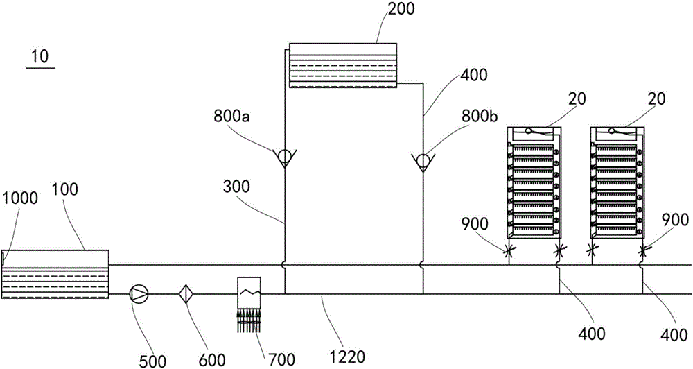
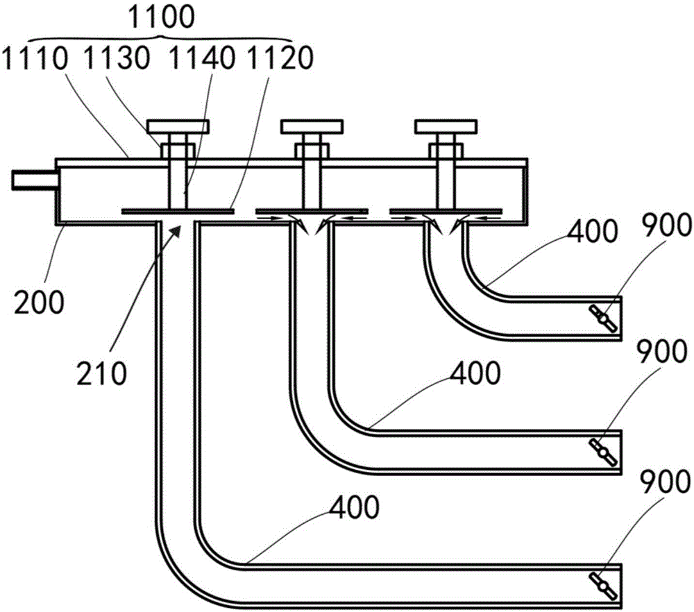
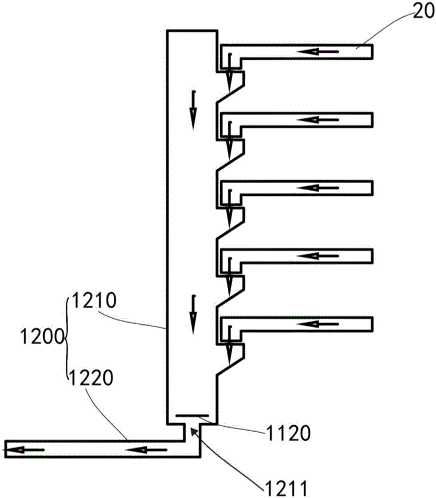
The invention discloses a circulation cooling system. The circulation cooling system comprises a first cooling tank, a second cooling tank, a connecting pipe, a driving pump, a radiator, control valves and a controller, wherein the first cooling tank and the second cooling tank are both used for accommodating coolants; the first cooling tank, the driving pump, the radiator and the second cooling tank are connected in series in sequence; the second cooling tank is also used for connecting to-be-cooled equipment through the connecting pipe; the control valves are arranged on the connection pipe between the second cooling tank and the to-be-cooled equipment; the to-be-cooled equipment is also connected to the first cooling tank through the connecting pipe; the height from the second cooling tank to the ground is higher than that from the first cooling tank to the ground; when the circulation cooling system is in use, the height from the to-be-cooled equipment to the ground is between the height from the second cooling tank to the ground, and the height from the first cooling tank to the ground; the controller is electrically connected to the driving pump and the radiator; and the radiator is used for performing heat dissipation on the coolants flowing through the radiator. By adoption of the circulation cooling system, the operating power of the pump can be lowered, and maintenance can be performed conveniently.

Description

technical field [0001] The invention relates to the field of liquid cooling, in particular to a circulating cooling system. Background technique [0002] With the rapid development of electronics and communication technology, power devices are rapidly developing in the direction of high performance and integration. The power of power devices is increasing, but the volume is gradually decreasing. Most power devices generate a lot of heat during operation and heat up instantaneously. fast, with detrimental effects on its performance. Most of the liquid cooling methods used by traditional high-power heating devices are: "oil tank-pump-cooling system-filter-high-power heating device-oil tank" closed cooling method. Although this method has certain advantages, it also has the following disadvantages: (1) The power of the pump operation is large. (2) It is inconvenient to maintain and increases the workload of maintenance. Contents of the invention [0003] Based on this, it ...

Claims


Application Information

Patent Timeline
Patent Type & Authority Applications(China)
IPC IPC(8): H05K7/20
CPCH05K7/20272
Inventor 王伟李景茂符颢译
Owner 广东西江数据科技有限公司
Learn More