washing machine

A cleaning machine and cleaning liquid technology, applied in the field of cleaning machines, can solve the problems of increasing the cost of use, increasing the labor intensity of operators, and the length of cleaning equipment, etc., to achieve the effects of reducing the length of land occupation, reducing the number of people, and reducing production costs

Active Publication Date: 2018-12-18
SUZHOU ENVIL MACHINERY
View PDF9 Cites 0 Cited by
  • Summary
  • Abstract
  • Description
  • Claims
  • Application Information

AI Technical Summary

Problems solved by technology

[0003] At present, the Chinese patent application number 200920248272.8 on the market discloses a washing and drying machine, and the Chinese patent application number 201410231168.3 discloses a cleaning machine, and the Chinese patent application number 201110297049.4 discloses an energy-saving cleaning machine. Equipment, although all can realize the cleaning to finished product in the manufacturing industry, yet the cleaning equipment in the prior art all has the same problem: 1, because existing cleaning equipment is all arranged in strips, facilitates finished product to pass through the conveyor belt The transportation goes through each cleaning link in turn, and because there are many cleaning links, the length of the cleaning equipment will be longer, so it is necessary to arrange an operator at both ends of the cleaning equipment to load and take out the material, otherwise only one operator will go back and forth between the two ends Running will greatly increase the labor intensity of the operator and increase the cost of use; 2. The existing cleaning equipment includes degreasing, cleaning, and drying. The degreasing effect is not good. It is necessary to increase the temperature during degreasing to make it easier for the degreasing agent to remove grease and other attachments. However, since the degreasing process is the first step in cleaning the finished product, and the drying is in the final process, it is necessary Heating machines are added at both ends, which increases the cost of production and use, which is not conducive to popularization and use

Method used


Image

  • washing machine
  • washing machine
  • washing machine

Examples


Embodiment Construction

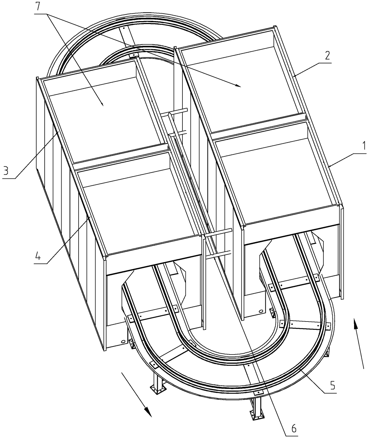
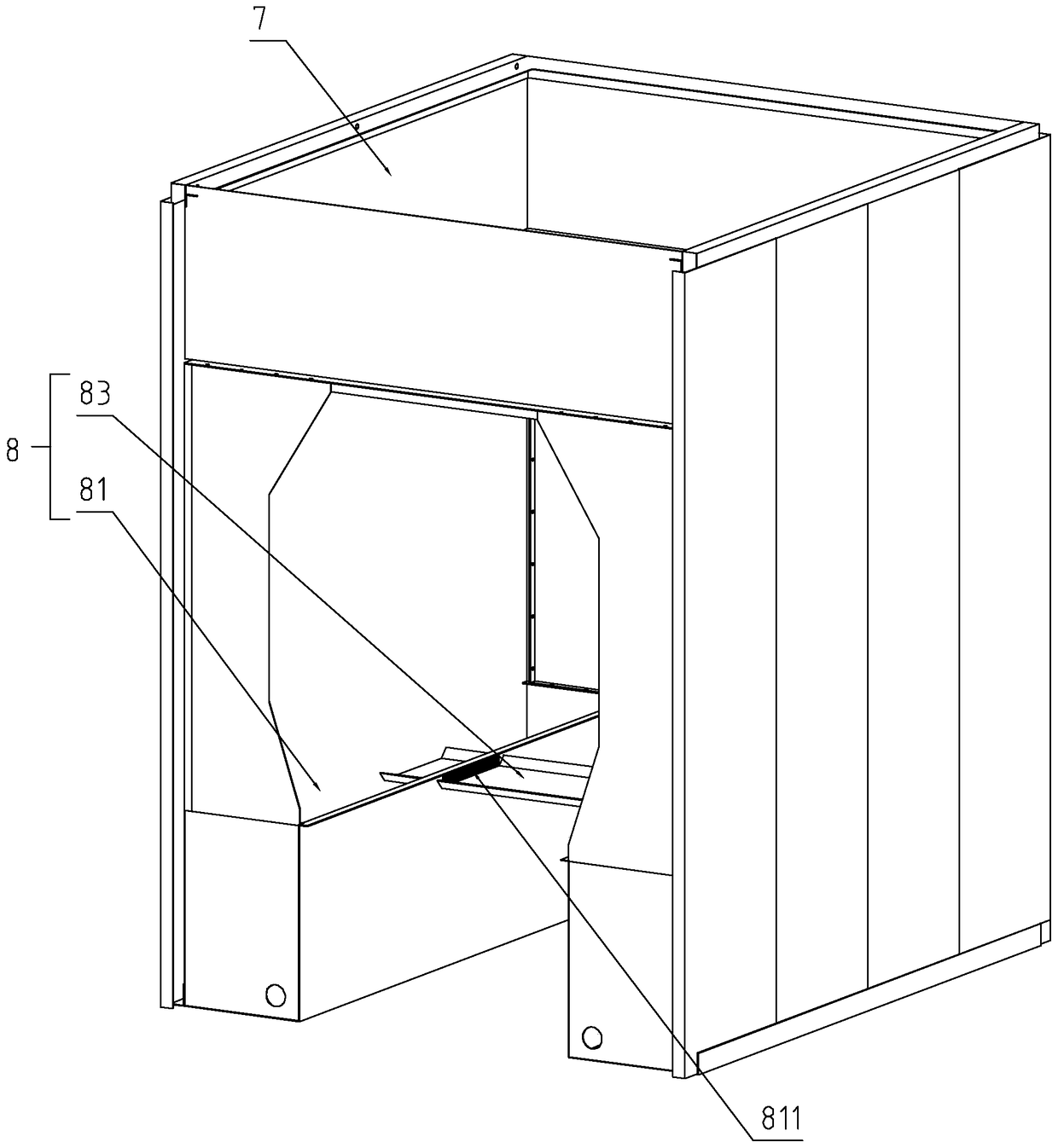
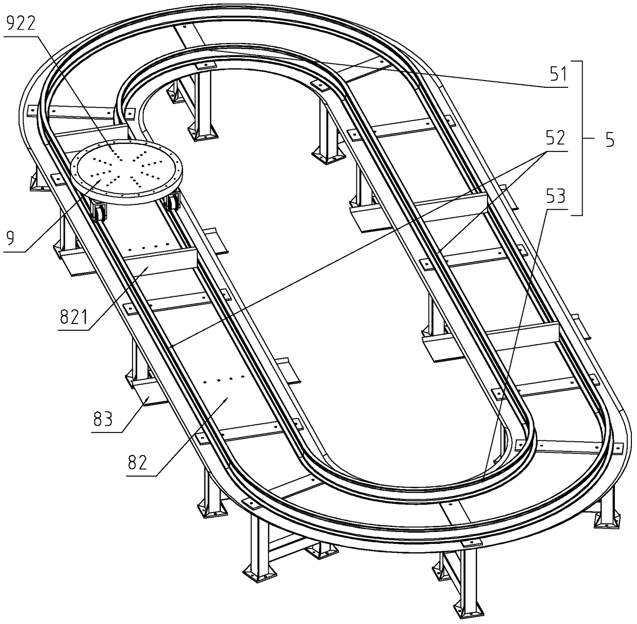
[0023] refer to Figure 1 to Figure 6 The embodiment of the cleaning machine will be further described.

[0024] A cleaning machine, comprising a degreasing device 1, a rough cleaning device 2, a fine cleaning device 3, a drying device 4, and a conveying track 5 for transporting products to be cleaned, and the conveying track 5 passes through the degreasing device 1 and the rough cleaning device 2 in sequence , fine cleaning device 3 and drying device 4, the above-mentioned devices all belong to the prior art, and its specific performance is: after the parts to be cleaned are placed on the conveying track 5, the conveying track 5 drives the parts to be cleaned to move, and when passing through the degreasing device 1 The nozzle inside sprays the degreasing agent onto the parts to be cleaned, and the degreasing agent saponifies, solubilizes, moistens, disperses, and emulsifies all kinds of oils, so that the oils are separated from the surface of the workpiece and become soluble...


PUM


Abstract

The invention discloses a cleaner. The key point of the technical scheme is that the cleaner comprises a degreasing device, a rough cleaning device, a finish cleaning device and a drying device as well as a conveying track for conveying a to-be-cleaned product. The conveying track successively penetrates through the degreasing device, the rough cleaning device, the finish cleaning device and the drying device. The conveying track comprises a turning rail between the head and the tail of the conveying track and the head and the tail of the conveying track of are arranged adjacently. According to the cleaner disclosed by the invention, the whole conveying track can be adjacent at the head and tail through the turning rail, so that the land-occupying length of the whole cleaning assembly line can be greatly reduced; the to-be-cleaned product enters from the head end of the conveying track and goes out from the adjacent tail end, so that loading and taking operations can be performed by only one operator, and therefore, the number of operators can be effectively reduced, and the production cost is favorably reduced.

Description

technical field [0001] The invention relates to the field of cleaning equipment, more specifically, it relates to a cleaning machine. Background technique [0002] In the manufacturing industry, such as the manufacturing of valves and various containers, the products will inevitably come into contact with dirt and grease such as mechanical lubricants, cutting oils, or difficult-to-clean anti-rust oils and stretching oils during the production process. Therefore, it is necessary to carry out precise cleaning of degreasing and decontamination of the finished product, which is used to effectively clean and prevent rust on the processed metal parts. The cleaning process is indispensable for cleaning equipment. [0003] At present, the Chinese patent application number 200920248272.8 on the market discloses a washing and drying machine, and the Chinese patent application number 201410231168.3 discloses a cleaning machine, and the Chinese patent application number 201110297049.4 d...

Claims


Application Information

Patent Timeline
Patent Type & Authority Patents(China)
IPC IPC(8): B08B9/30B08B3/02
CPCB08B3/022B08B9/30
Inventor 王雪峰
Owner SUZHOU ENVIL MACHINERY
Why Eureka
Try Eureka