Braking control method and system for vehicle and vehicle

A braking control and vehicle technology, applied in the vehicle braking control method, system and vehicle field, can solve the problems of large vehicle installation space, complex locking mechanism, potential safety hazards, etc., so as to reduce installation and improve functional integration. , The effect of improving driving convenience and safety

Active Publication Date: 2017-04-05
GREAT WALL MOTOR CO LTD
View PDF5 Cites 18 Cited by
  • Summary
  • Abstract
  • Description
  • Claims
  • Application Information

AI Technical Summary

Problems solved by technology

[0004] 1) When the driver forgets to pull up the handbrake system and parks on the slope with the P gear, due to the weight of the car, the clearance of the locking mechanism of the P gear will be eliminated, and a large friction force will be generated inside the locking mechanism. The movement resistance of the shift handle is increased, so when starting again, it is difficult for the driver to take off from the P gear for driving operation
[0005] 2) The locking mechanism of the P gear of the vehicle equipped with an automatic transmission is complicated, and the installation space of the vehicle will be occupied. , higher installation and maintenance costs
[0006] 3) Only relying on locking the output shaft of the automatic transmission to prevent the rolling of the driving wheels cannot effectively solve the danger of the vehicle slipping due to insufficient power when starting on a slope. In serious cases, it will cause an accident and pose a safety hazard

Method used


Image

  • Braking control method and system for vehicle and vehicle
  • Braking control method and system for vehicle and vehicle
  • Braking control method and system for vehicle and vehicle

Examples


Embodiment Construction

[0038] It should be noted that, in the case of no conflict, the embodiments of the present invention and the features in the embodiments can be combined with each other.

[0039] The present invention will be described in detail below with reference to the accompanying drawings and examples.

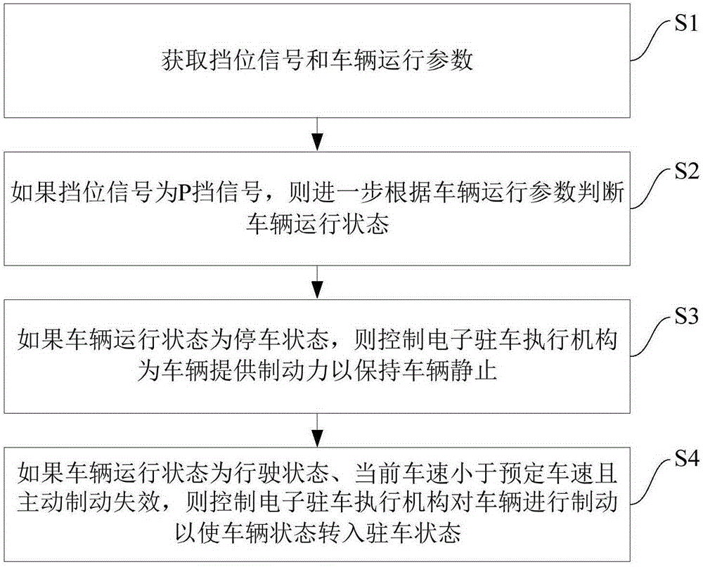
[0040] figure 1 is a flow chart of a braking control method for a vehicle according to an embodiment of the present invention.

[0041] In the following description, a vehicle is, for example, a vehicle on which an automatic transmission is mounted.

[0042] Such as figure 1 As shown, the brake control method of a vehicle according to an embodiment of the present invention includes the following steps:

[0043] S1: Obtain the gear position signal and vehicle operating parameters.

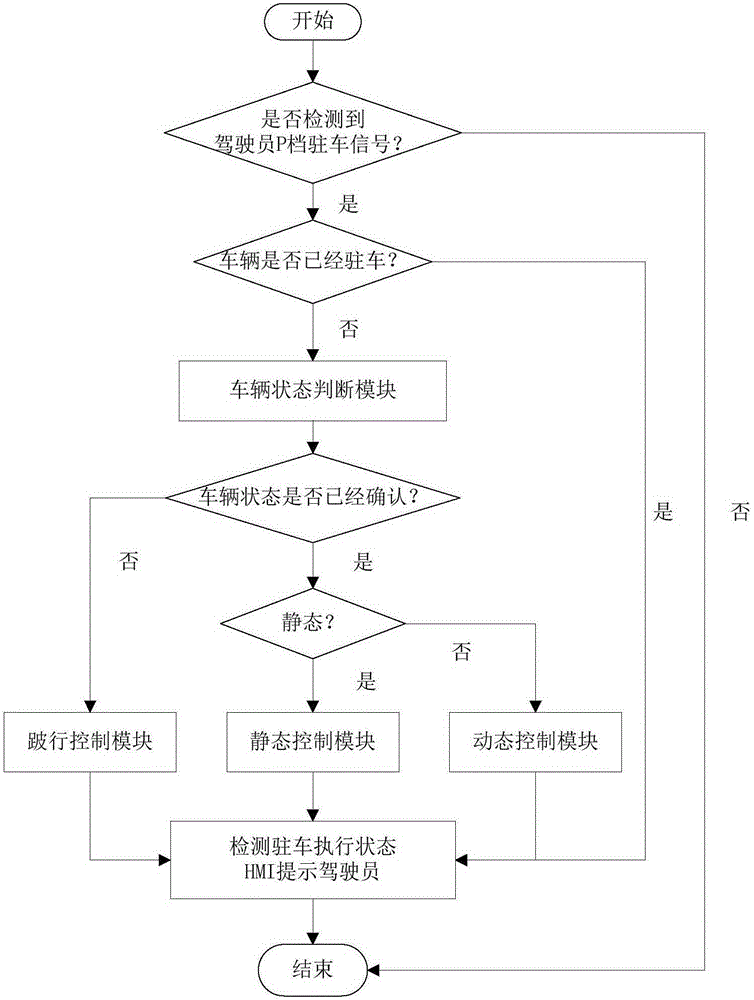
[0044] In one embodiment of the present invention, as figure 1 shown, combined with figure 2 , for example, the gear position signal of the vehicle can be obtained through the gear shifter input unit of t...


PUM


Abstract

The invention provides a braking control method and system for a vehicle and the vehicle. The method includes the steps that a gear position signal and vehicle running parameters are acquired; if the gear position signal is a neutral gear signal, the running state of the vehicle is further judged according to the vehicle running parameters; if the running state of the vehicle is a parking state, an electronic parking execution mechanism is controlled to provide the braking force for the vehicle so as to keep the vehicle static; and if the running state of the vehicle is a driving state, a current vehicle speed is small than a preset vehicle speed and active braking loses efficacy, the electronic parking execution mechanism is controlled to brake the vehicle so as to make the vehicle state turned into the parking state. By means of the method, the vehicle electronic control function integration degree can be improved, the vehicle installing and maintaining cost is reduced, meanwhile, the P gear function is extra expanded, and the vehicle driving convenience and safety is improved.

Description

technical field [0001] The invention relates to the technical field of automobiles, in particular to a vehicle braking control method, system and vehicle. Background technique [0002] When parking a vehicle equipped with an automatic transmission, step on the brake pedal first, and then place the electronic shifter handle at the parking gear (P gear) after the vehicle has stopped, at this time the automatic transmission control unit passes The P gear signal is detected to drive a corresponding locking mechanism. The locking mechanism here is, for example, a combination of a motor and a ratchet, a combination of a solenoid valve push rod, and the like. [0003] However, existing vehicles with automatic transmissions have the following disadvantages when parking: [0004] 1) When the driver forgets to pull up the handbrake system and parks on the slope with the P gear, due to the weight of the car, the clearance of the locking mechanism of the P gear will be eliminated, and ...

Claims


Application Information

Patent Timeline
Patent Type & Authority Applications(China)
IPC IPC(8): B60T7/12
CPCB60T7/12B60T2201/06
Inventor 唐彩明李琦张瀛赵玉静董蒿松信瑛南应世明李阳泰
Owner GREAT WALL MOTOR CO LTD
Why Eureka
Try Eureka