
A Rotor Structure for Improving Air Gap Flux Density Waveform of 2-pole Self-starting Permanent Magnet Motor

An air-gap magnetic density, permanent magnet motor technology, applied in the magnetic circuit shape/style/structure, manufacturing stator/rotor body, magnetic circuit rotating parts, etc., can solve the problem of weakening the harmonic magnetic field, complex magnetic pole structure, increasing motor Stator harmonic current, harmonic copper loss, stator core harmonic loss, etc., to optimize the air-gap flux density waveform, overcome the limited rotor space, and reduce the torque ripple of the motor

Active Publication Date: 2019-09-06
DANDONG SHANCHUAN ELECTRICAL ENG
View PDF5 Cites 0 Cited by
  • Summary
  • Abstract
  • Description
  • Claims
  • Application Information

AI Technical Summary

Problems solved by technology

[0004] At present, most self-starting permanent magnet motors adopt a uniform air gap structure, and the air gap magnetic field contains a large number of harmonics. When the permanent magnets are arranged unreasonably in the rotor, the harmonics in the air gap flux density will be more serious, making the permanent magnet The harmonic content in the electromotive force of the motor is relatively large, which increases the harmonic current in the motor stator, the harmonic copper loss and the harmonic loss in the stator core, and there are also harmonic iron loss, harmonic current and harmonic copper loss in the rotor. consumption, which affects the further improvement of the efficiency of the permanent magnet motor; in addition, the harmonic magnetic field and harmonic current will also generate additional torque fluctuations, causing vibration and noise of the motor
[0005] Due to the particularity of the rotor structure of the 2-pole self-starting permanent magnet motor, in order to increase the amount of magnetic steel placed in the rotor, the magnetic pole structure is generally more complicated. The traditional "one", "U", "V" and "W" structures are very complex. Difficult to meet the design requirements, it is necessary to adopt a combination of various structures
[0006] At present, in order to reduce the influence of the magnetic wave magnetic field in the no-load air gap magnetic field on the performance of the motor, the self-starting permanent magnet motor mainly uses the arrangement of the permanent magnets in the rotor and the reasonable design of the pole arc width to weaken the harmonic in the air gap. Wave magnetic field and the purpose of reducing torque ripple, but the weakening effect of this method is limited
In order to make the magnetic field of the motor closer to sinusoidal, Xu Yinglei of Southwest Jiaotong University proposed a self-starting permanent magnet motor with an eccentric air gap structure whose magnetic pole shape is a single arc, and Liu Mingji of North China Electric Power University proposed a rotor structure with three The self-starting permanent magnet motor with a segmented arc structure optimizes the air gap flux density waveform through the pole arc eccentric method. Although the optimization goal is achieved, the outer circle shape of the rotor of the motor is complex, which increases the difficulty of processing the motor.

Method used


Image

  • A Rotor Structure for Improving Air Gap Flux Density Waveform of 2-pole Self-starting Permanent Magnet Motor
  • A Rotor Structure for Improving Air Gap Flux Density Waveform of 2-pole Self-starting Permanent Magnet Motor
  • A Rotor Structure for Improving Air Gap Flux Density Waveform of 2-pole Self-starting Permanent Magnet Motor

Examples


Embodiment

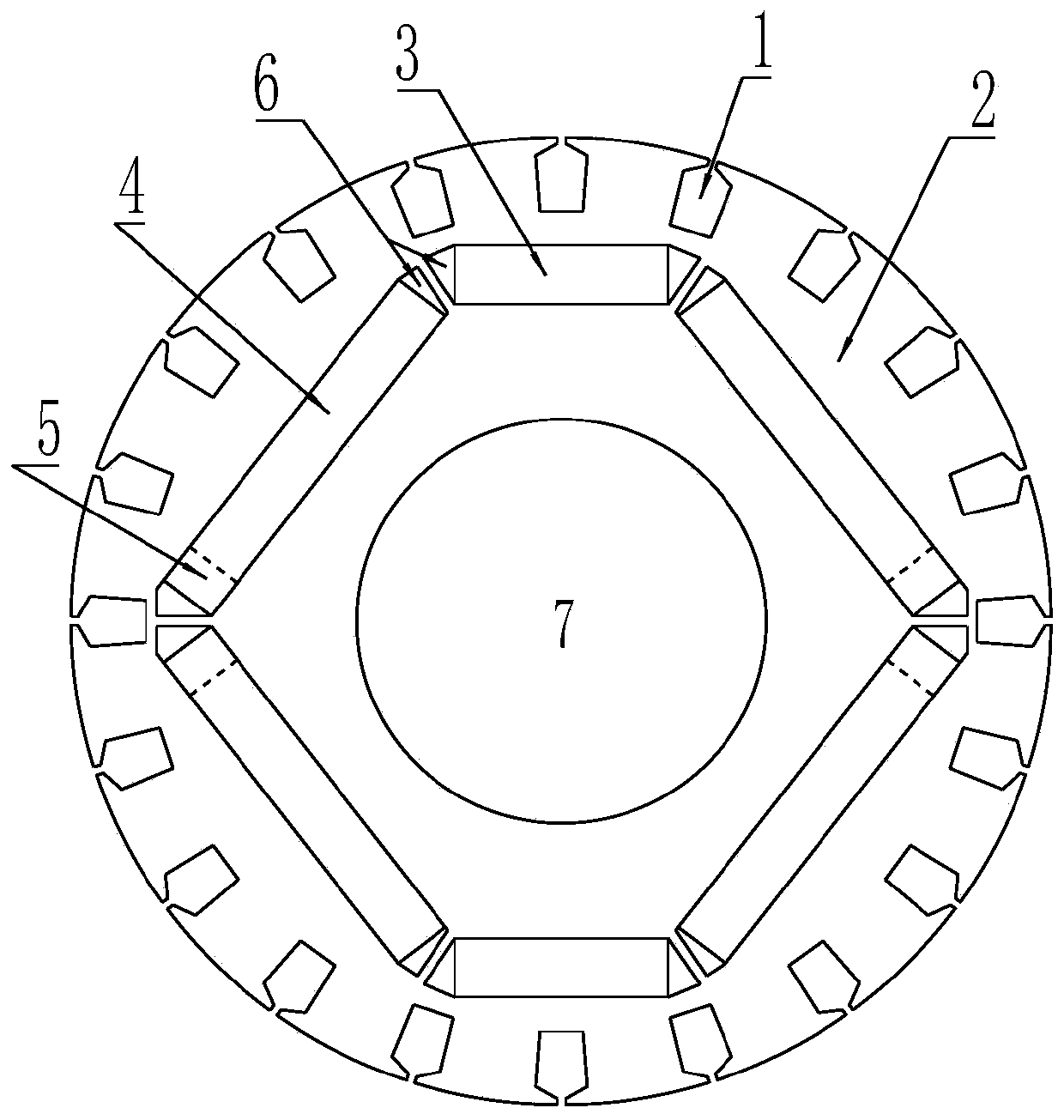
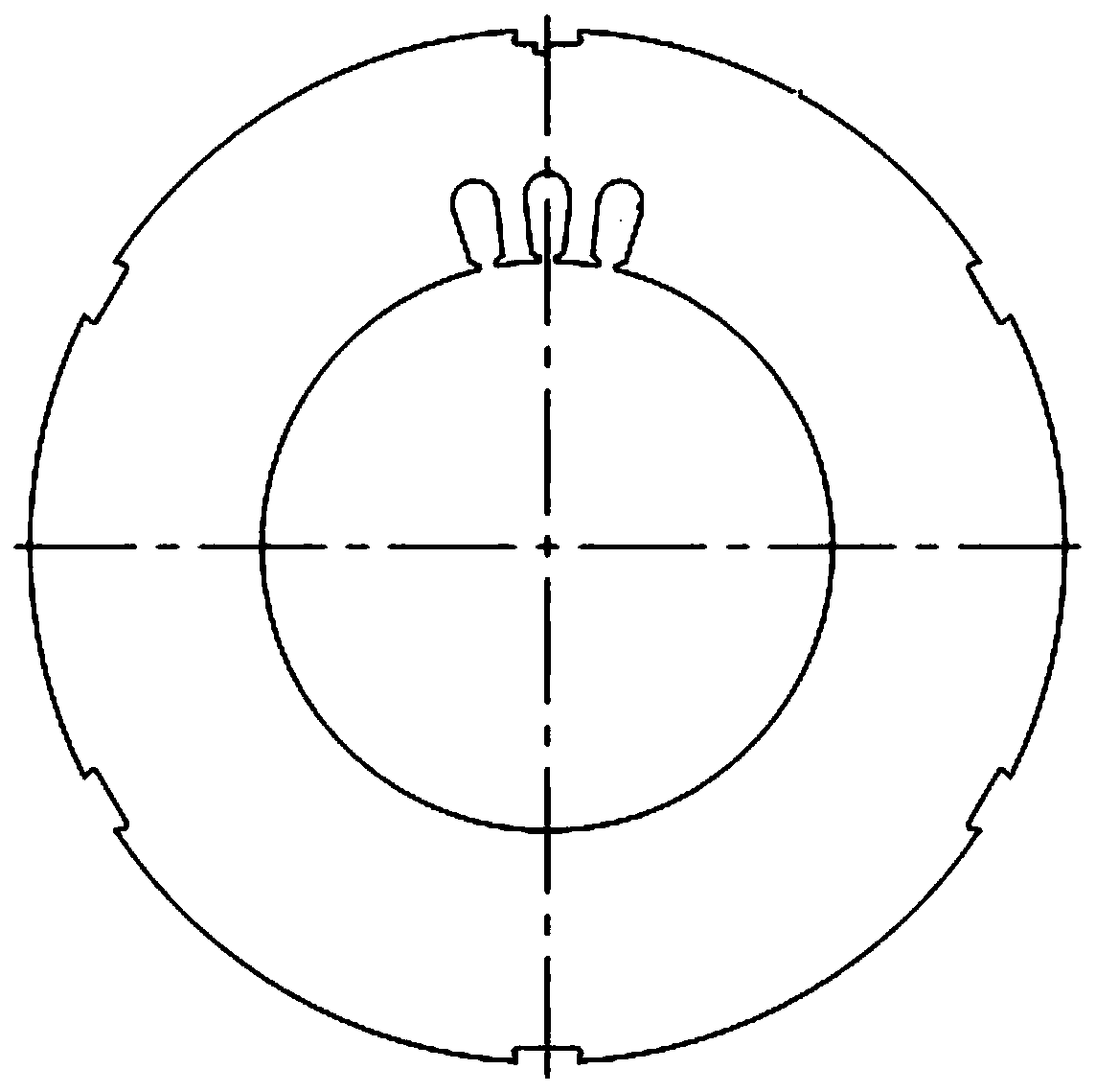
[0031] Take a 132 frame size 7.5kW, 2-pole self-starting permanent magnet motor as an example, the stator of the motor adopts the standard Y2 series stator punching, such as figure 2 Shown; Rotor stamping adopts a kind of structure that the present invention provides to improve 2-pole self-starting permanent magnet motor air-gap magnetic density waveform, as figure 1 As shown, it includes a rotor core 2 with several squirrel cage slots 1 and permanent magnets installed in the permanent magnet slots. The permanent magnets under the two poles all adopt a three-stage inverted "U"-shaped magnetic circuit structure, which is divided into the middle One section of permanent magnet 3 and two sections of side permanent magnets 4, between two adjacent sections of permanent magnets is an air groove 6, and the three sections of permanent magnets are left and right symmetrical about the center line of the middle section of permanent magnets 3, and the two sections of side permanent magnet...


PUM


Abstract

The invention, which belongs to the technical field of motor fittings, particularly relates to a rotor structure capable of improving a gap flux density waveform of a two-pole self-starting permanent-magnet motor. The rotor structure comprises a rotor iron core having a plurality of mouse case slots and permanent magnets installed in permanent-magnet slots. The permanent magnets under two poles employ three-segment type inverted-U-shaped magnetic circuit structures and each of the permanent magnets includes an intermediate-segment permanent magnet and two segments of side permanent magnets; air slots are formed between the two adjacent segments of permanent magnets; the three segments of permanent magnets are arranged in a left-right symmetric mode relative to the central lines of the intermediate-segment permanent magnets; and end portions, far away from mounting slots of the intermediate-segment permanent magnets, of mounting slots of the two segments of side permanent magnets are non-magnetic-conductive material filling parts. The whole rotor structure is in a left-right-symmetric mode relative to the central lines of the intermediate-segment permanent magnets and the rotor is installed at a rotating shaft. Therefore, the gap flux density waveform of the motor can be optimized. On the basis of sinusoidal processing of the gap flux density waveform of the motor, the harmonic contents in the air-gap field and the stator winding can be reduced, the counter-electromotive-force waveform can be optimized, the motor efficiency can be improved; and the motor torque pulsation can be reduced.

Description

technical field [0001] The invention belongs to the technical field of motor accessories, and in particular relates to a rotor structure for improving the air-gap magnetic density waveform of a 2-pole self-starting permanent magnet motor. Background technique [0002] Due to the advantages of simple structure and low price of asynchronous motors, AC asynchronous motors have been widely used in various industrial fields. However, the asynchronous motor needs excitation current provided by the stator winding, and its power factor is low, and due to the existence of rotor aluminum loss (copper loss), the efficiency of the motor is not high, especially for small asynchronous motors or when the motor is lightly loaded. Compared with asynchronous motors, self-starting permanent magnet motors have obvious advantages. It has the characteristics of high efficiency, high power factor, good force index, small size, light weight, and low temperature rise. It is an ideal choice to replac...

Claims


Application Information

Patent Timeline
Patent Type & Authority Patents(China)
IPC IPC(8): H02K1/27H02K15/03
Inventor 刘岚张炳义辛洪平刘建礼周磊张兴龙蒋贵祥徐超鄂宇蒋志玲孙炜周世峰吴国龙刘晓生苏艳莎
Owner DANDONG SHANCHUAN ELECTRICAL ENG
Learn More