Mixed xylene deolefination refining device and method

A technology for removing olefins from xylene and mixing xylenes, applied in chemical instruments and methods, purification/separation of hydrocarbons and hydrocarbons, etc., can solve the problems of frequent switching of pipelines, affecting product quality, etc. , Extend the service cycle, and improve the effect of comprehensive benefits

Active Publication Date: 2017-04-19
CHINA PETROLEUM & CHEM CORP
View PDF4 Cites 1 Cited by
  • Summary
  • Abstract
  • Description
  • Claims
  • Application Information

AI Technical Summary

Problems solved by technology

The advantage of the former is that the high molecular product produced by the polymerization of deolefin refining agent (activated clay, modified clay or molecular sieve catalyst) can be cut off to the heavy fraction in the bottom of the tower through the mixed xylene tower. The disadvantage is that the whole fraction is refined, which increases the consumption of refining agent
The advantage of the latter is that it is only for the deolefinization of C8 fractions, which reduces the processing capacity and catalyst consumption. The disadvantage is that in order to avoid generating too many high-boiling components that affect product quality, the operating temperature of the refined preparation is reduced.
[0004] Both the patent CN103044184A and the patent CN103044177A optimize the operation by adjusting the heat exchange process and reforming reaction conditions, that is, by switching the mixed xylene clay tower before and after the tower mode and adjusting the reforming reaction conditions to improve the mixed xylene clay tower feed, Improve the yield of mixed xylene and prolong the service life of the clay tower, but there are also disadvantages such as more valves and pipelines and frequent switching

Method used


Image

  • Mixed xylene deolefination refining device and method
  • Mixed xylene deolefination refining device and method

Examples


Embodiment 1

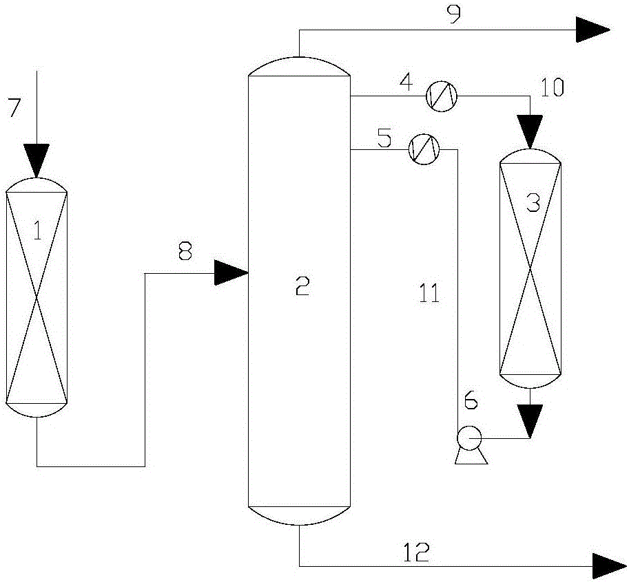
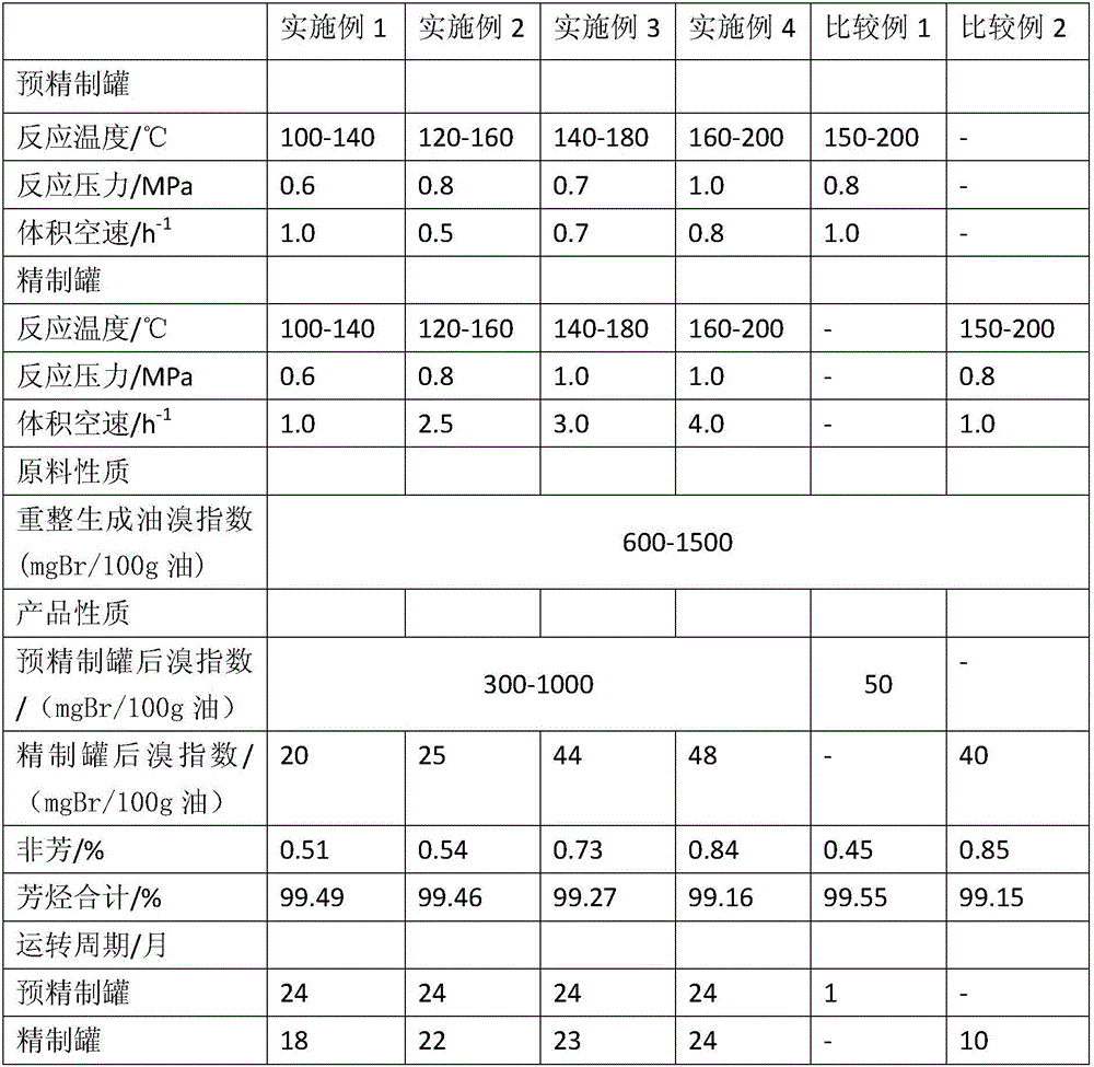
[0024] The reformed oil fraction first enters the pre-refining tank 1, at reaction temperature: 100-140°C, reaction pressure: 0.6MPa, volume space velocity: 1.0h -1 Under certain conditions, after removing part of the olefins, enter the mixed xylene fractionation tower 2 for fractionation, and draw out the mixed C8 cut from the side line above the first tray from the top to the bottom of the mixed xylene fractionation tower 2, and pass through the feed heat exchanger 4 After cooling down, enter the refining tank 3, at reaction temperature: 100-140°C, reaction pressure: 0.6MPa, volumetric space velocity: 1.0h -1 Under the conditions, after removing olefins, return to the mixed xylene fractionation tower 2 on the 6th tray from top to bottom after the centrifugal pump 6 and the discharge heat exchanger 5 heat up, and the top of the tower outputs the mixed xylene product, Polymer with tower kettle C9 + Heavy components are discharged.

Embodiment 2

[0026] The reformed oil fraction first enters the pre-refining tank 1, at reaction temperature: 120-160°C, reaction pressure: 0.8MPa, volume space velocity: 0.5h -1 Under certain conditions, after removing part of the olefins, enter the mixed xylene fractionation tower 2 for fractionation, and draw out the mixed C8 fraction from the top of the fifth tray from the top to bottom of the mixed xylene fractionation tower 2, and pass through the feed heat exchanger 4 After cooling down, enter the refining tank 3, at reaction temperature: 120-160°C, reaction pressure: 0.8MPa, volumetric space velocity: 2.5h -1 Under the conditions, after removing olefins, return to the mixed xylene fractionation tower 2 on the 10th tray from top to bottom after the centrifugal pump 6 and the discharge heat exchanger 5 heat up, and the mixed xylene product is produced at the top of the tower. Polymer with tower kettle C9 + Heavy components are discharged.

Embodiment 3

[0028] The reformed oil fraction first enters the pre-refining tank 1, at the reaction temperature: 140-180°C, reaction pressure: 0.7MPa, volume space velocity: 0.7h -1 Under certain conditions, after removing part of the olefins, enter the mixed xylene fractionation tower 2 for fractionation, from the mixed xylene fractionation tower 2 from the top to the bottom of the second plate, the side line draws out the mixed C8 fraction, and passes through the feed heat exchanger 4 After cooling down, enter the refining tank 3, at reaction temperature: 140-180°C, reaction pressure: 1.0MPa, volumetric space velocity: 3.0h -1 Under the conditions, after removing olefins, return to the mixed xylene fractionation tower 2 on the 7th tray from top to bottom after the centrifugal pump 6 and the discharge heat exchanger 5 heat up, and the top of the tower outputs the mixed xylene product, Polymer with tower kettle C9 + Heavy components are discharged.


PUM

PropertyMeasurementUnit
densityaaaaaaaaaa
relative humidityaaaaaaaaaa
densityaaaaaaaaaa

Abstract

The invention discloses a mixed xylene deolefination refining device and method. The device comprises a pre-refining tank, a mixed xylene fractionation column, a refining tank, a feeding heat exchanger, a discharging heat exchanger and a centrifugal pump. A C8 fraction is withdrawn from the side line above some column plate in 1-5 column plates counted from the top of the mixed xylene fractionation column downwards and used for feeding of the top of the refining tank, and tank bottom discharging returns from the side line above some column plate in 6-10 column plates counted from the top of the mixed xylene fractionation column downwards; and the top of the refining tank is at the 5-column-plate distance from the withdrawing position of the side line of the mixed xylene fractionation column, and the bottom of the refining tank is at the 5-column-plate distance from the return position of the side line of the mixed xylene fractionation column, mixed xylene products are produced from the top of the column, and polymers are discharged along with column reactor C9+ heavy components. By the adoption of the mixed xylene deolefination refining device and method, the purpose that the polymers can be separated without additionally arranging a separation column or other equipment and the qualified mixed xylene products are obtained is achieved; the service cycle of a catalyst can be prolonged, the cost is lowered, and high-quality chemical raw materials are obtained; and the good comprehensive benefits are obtained.

Description

technical field [0001] The invention relates to the field of petrochemical industry, in particular to a device and method for refining mixed xylene deolefins. Background technique [0002] The mixed xylene product is one of the important chemical basic products, which is obtained from the reforming product oil fractionation tower of the continuous reforming unit. The oil produced by catalytic reforming is rich in aromatics and solvent oil fractions, but also contains a small amount of olefins. These olefins are active and easy to form colloids; the presence of olefins will also affect some subsequent processing processes such as extraction of aromatics. In order to produce qualified aromatics and solvent oil products, olefins must be removed. At present, the widely used deolefin refining unit in industry adopts hydrogenation and granular clay process for removal. The precious metals used in hydrorefining are expensive, and the presulfurization of catalysts will generate s...

Claims


Application Information

Patent Timeline
Patent Type & Authority Applications(China)
IPC IPC(8): C07C7/00C07C7/04C07C7/12C07C7/13C07C15/08
CPCC07C7/005C07C7/04C07C7/12C07C7/13C07C15/08
Inventor 冯保杰程建侯志忠孙学锋于焕良
Owner CHINA PETROLEUM & CHEM CORP
Why Eureka
Try Eureka