Laser projector and depth camera thereof

A laser projector and light-emitting element technology, applied in the optical field, can solve the problems of reducing the irrelevance of laser patterns, and achieve the effects of improving the irrelevance, speed and accuracy

Inactive Publication Date: 2017-04-19
SHENZHEN ORBBEC CO LTD
View PDF4 Cites 32 Cited by
  • Summary
  • Abstract
  • Description
  • Claims
  • Application Information

AI Technical Summary

Problems solved by technology

[0004] The technical problem mainly solved by the present invention is to provide a laser projector and its depth camera to solve the problem in the prior a

Method used


Image

  • Laser projector and depth camera thereof
  • Laser projector and depth camera thereof
  • Laser projector and depth camera thereof

Examples


Embodiment Construction

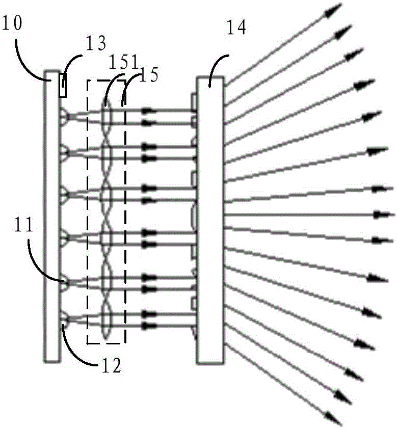
[0030] refer to figure 1 , figure 1 It is a structural schematic diagram of an embodiment of the laser projector of the present invention.

[0031] The laser projector in this embodiment includes a substrate 10, at least two light emitting elements 11 and 12, a controller 13 and a diffractive optical element 14;

[0032] Wherein, the diffractive optical element 14 is arranged at a position separated from the substrate 10 by a first distance; at least two light emitting elements 11, 12 are fixed on the side of the substrate 10 facing the diffractive optical element 14;

[0033] At least two light-emitting elements 11, 12 emit laser light under the control of the controller 13, and at least two light-emitting elements 11, 12 have at least two different light-emitting areas; the diffractive optical element 14 is used to combine at least two light-emitting elements 11, 12 The laser beam emitted by 12 expands and emits a laser pattern into the space.

[0034] The laser projector...


PUM


Abstract

The invention discloses a laser projector and a depth camera thereof. The laser projector includes a substrate, at least two light emitting elements, a controller and a diffractive optical element. The diffractive optical element is arranged at a position at a first distance from the substrate. The at least two light emitting elements are fixed at one side, facing the diffractive optical element, of the substrate. The at least two light emitting elements emit laser under the control of the controller, and have at least two different light emitting areas. The diffractive optical element is used for expanding laser beams sent by the at least two light emitting elements and then emitting laser patterns to the air. The laser projector meets the output power requirements by arranging the at least two light emitting elements, improves the irrelevance of the laser patterns by arranging at least two light emitting areas, and further improves the speed and the precision of obtaining the depth image of the laser pattern of the depth camera thereof.

Description

technical field [0001] The invention relates to the field of optics, in particular to a laser projector and a depth camera thereof. Background technique [0002] Laser projectors are used to emit set optical patterns to the target space, and are widely used in the field of optical-based three-dimensional measurement. A laser projector generally consists of a light source, a collimating mirror, and a diffractive optical element. The light source can be a single edge-emitting laser light source or an area array laser light source composed of multiple vertical cavity surface-emitting lasers. [0003] A laser projector based on a single edge-emitting laser source can emit a laser pattern with high irrelevance, but its volume will increase significantly with the increase of output power, and the uniformity of the laser pattern is poor; A laser projector with at least two vertical-cavity surface-emitting laser sources can emit a laser pattern with the same power and higher unifor...

Claims


Application Information

Patent Timeline
IPC IPC(8): G01B11/25G02B27/42G02B27/48
CPCG02B27/4233G01B11/254G02B27/48
Inventor 黄源浩刘龙肖振中许星
Owner SHENZHEN ORBBEC CO LTD
Why Eureka
Try Eureka