Supercharge Your Innovation With Domain-Expert AI Agents!

Design method of continuous spiral phase plate

A spiral phase plate and design method technology, applied in the field of optics, can solve the problems of reducing the optical performance of the vortex light field, the influence of optical conversion efficiency, and large processing errors, so as to meet the requirements of optical performance and solve the problems of low output performance and low cost Effect

Inactive Publication Date: 2019-08-02
成都精密光学工程研究中心
View PDF3 Cites 0 Cited by
  • Summary
  • Abstract
  • Description
  • Claims
  • Application Information

AI Technical Summary

Problems solved by technology

According to the characteristics of the preparation process, at present, the continuously distributed spiral rising slope is generally designed in steps, and the surface shape of each step is distributed as a plane. The more the number of steps, the closer to the ideal continuous surface structure, the better the optical performance. For overlay engraving process, the more steps, the more process flow is required, the processing equipment with high alignment accuracy and process certainty is required, and the processing cost is high
More importantly, since the multi-step design itself has cut off the continuity of the spiral rising slope, the optical performance of the vortex light field is reduced, and the optical conversion efficiency is also greatly affected.
However, the ideal spiral phase plate has a jumping section with an infinite gradient. If the continuous polishing process is used to process it directly, the processing error will be large.

Method used


Image

  • Design method of continuous spiral phase plate
  • Design method of continuous spiral phase plate
  • Design method of continuous spiral phase plate

Examples


Embodiment Construction

[0036] Below in conjunction with embodiment the present invention is further described.

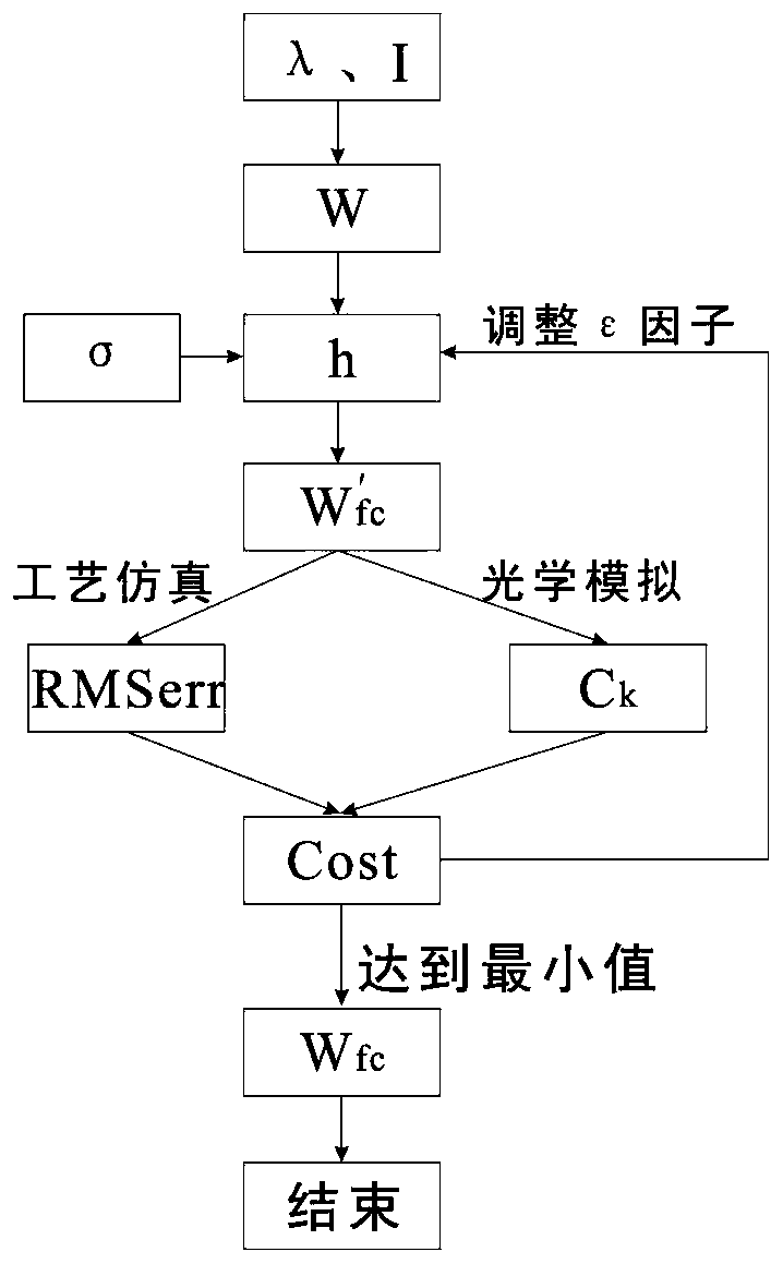
[0037] Continuous spiral phase plate design method, the process is as follows figure 1 as shown,

[0038] Step A: Determine the wavelength of the laser used in the design of the continuous spiral phase plate λ = 800nm, the aperture S = 180mm, and the corresponding light field E of the laser 1 for plane light;

[0039] Step B: The target image distribution I is a hollow annular focal spot, the imaging distance L is the focal length of the focusing lens, L=2000mm, that is, the imaging plane is the focal plane;

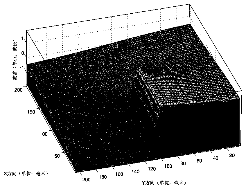
[0040] Step C: Determine the topological charge l=1 and size D=200mm of the ideal spiral phase plate according to the aperture S and the target image distribution I, and its three-dimensional structure is as follows figure 2 As shown, the value range of the wavefront W of the ideal spiral phase plate is (-λ,λ), and the wavefront W consists of two parts: a continuous spiral risin...


PUM


Abstract

The present invention discloses a continuous type helical phase plate design method and belongs to the optics field. The method includes the following steps that: 1) laser wavelength and corresponding optical field distribution are determined; 2) an imaging distance and a target image are determined; 3) the overall size and the number of the topological charges of a helical phase plate are determined; 4) the morphological features of a removal function are extracted according to a continuous polishing process; 5) a digital filter for smoothing processing is designed according to the step 2) and the step 3); 6) continuous processing is performed on an ideal helical phase plate according to the digital filter obtained in the step 5), so that a continuous helical phase plate can be obtained; 7) simulating calculation is performed on the continuous helical phase plate according to continuous polishing process software, so that a residual error wavefront can be obtained; 8) light field simulation and functional verification are performed on the continuous helical phase plate through using a diffraction theory; and 9) the step 5) to the step 8) are repeated, a preset requirement is satisfied, and design is completed. With the continuous type helical phase plate design method of the invention adopted, the design of the continuous type helical phase plate with high optical performance and conversion efficiency is realized. The phase plate designed by using the continuous type helical phase plate design method of the invention is simple in manufacturing process and low in cost.

Description

[0001] Technical field [0002] The invention relates to the design of optical elements, especially the design of a spiral phase plate, and belongs to the field of optical technology. Background technique [0003] At present, the helical phase plate is a transparent glass plate whose thickness is proportional to the rotation azimuth angle, which can convert a high-power planar beam into a vortex beam with orbital angular momentum. This high-power vortex beam generates femtosecond Vortex laser pulses, excited annular plasma wakefields, and positron-electron acceleration have important applications in high-power physics research fields. These studies have proposed higher optical performance for the helical phase plate that generates vortex beams. Therefore, there is an urgent need for the optimal design and precision machining of the spiral phase plate. The ideal spiral phase plate is composed of two parts: a continuous spiral rising slope and a discontinuous jump section. Acc...

Claims


Application Information

Patent Timeline
Patent Type & Authority Patents(China)
IPC IPC(8): G02B27/00G02B5/30
CPCG02B5/3083G02B27/0012
Inventor 张远航温圣林唐才学王健张清华刘民才杨春林颜浩罗子健李昂
Owner 成都精密光学工程研究中心
Features
  • R&D
  • Intellectual Property
  • Life Sciences
  • Materials
  • Tech Scout
  • Unparalleled Data Quality
  • Higher Quality Content
  • 60% Fewer Hallucinations
Learn More