Drive control system for endoscope stapler

A transmission control and stapler technology, applied in medical science, surgery, surgical fixation nails, etc., can solve the problems of affecting the recovery effect, increasing the patient's burden, uneven force, etc., and achieve the effect of saving internal space structure and reducing costs

Active Publication Date: 2017-04-26
B J ZH F PANTHER MEDICAL EQUIP
View PDF7 Cites 5 Cited by
  • Summary
  • Abstract
  • Description
  • Claims
  • Application Information

AI Technical Summary

Problems solved by technology

[0003] Existing endoscopic staplers do not have an external power source, and only rely on manual firing by the doctor, resulting in unstable firing force, uneven cutting, and burrs on the tissue, which in turn causes uneven stress on the tissue after anastomosis, resulting in the elasticity of the tissue itself. become different, affecting postoperative recovery
In order to solve this problem, there has been an electric stapler with a power source, but one of the existing electric endoscopic staplers is a semi-electric endoscopic stapler, part of the operation is controlled manually, and part of the operation is powered by a motor. Anastomosis; the other is the all-electric intelligent endoscopic stapler, which is commonly composed of batteries, MCU control circuit systems, motors, and transmission structure systems. The combination of motors has a complex structure and high manufacturing costs. Many operations are used once or repeated for a small number of times, which increases the burden on patients and affects the wide application of products.

Method used


Image

  • Drive control system for endoscope stapler
  • Drive control system for endoscope stapler
  • Drive control system for endoscope stapler

Examples


Embodiment 1

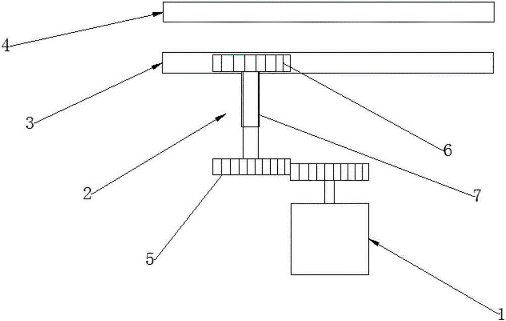
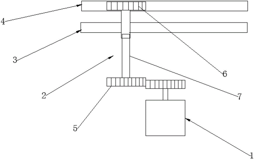
[0047] This embodiment provides a transmission control system of an endoscopic stapler, including a driving part 1, a transmission conversion part 2, a first driven assembly 3 and a second driven assembly 4; the transmission conversion part 2 is a movable part and includes The first transmission part and the second transmission part, the first transmission part of the transmission conversion part 2 is always connected with the drive part 1; the second transmission part of the transmission conversion part 2 communicates with the first driven assembly 3 and the second The transmission part drives the first driven assembly 3, and the first driven assembly 3 controls the first series of transmission control actions of the endoscopic stapler; after the transmission conversion part 2 performs A action, the second transmission part and the second driven The assembly 4 is connected and the second transmission part drives the second driven assembly 4, and the second driven assembly 4 co...


PUM


Abstract

The invention discloses a drive control system for an endoscope stapler. The drive control system comprises a driving part, a drive transform part, a first driven assembly and a second driven assembly, wherein the drive transform part is an acting part and comprises a first drive component and a second drive component; the first drive component of the drive transform part is always connected with the driving part; the second drive component of the drive transform part is connected with the first driven assembly, and the second drive component drives the first driven assembly; the first driven assembly controls the first series of drive control actions of the endoscope stapler; and after the drive transform part makes an action A, the second drive component is connected with the second driven assembly and drives the second driven assembly, and the second driven assembly controls the second series of drive control actions of the endoscope stapler. The drive control defect of the existing stapler is overcome, multiple types of drive control can be realized by utilizing a motor, and multiple switching control requirements are met.

Description

technical field [0001] The invention relates to the field of surgical medical instruments, in particular to a transmission control system of an endoscopic stapler. Background technique [0002] The laparoscopic stapler includes an end effector and a control system, the control system controls the operations of clamping, cutting and stapling the tissue after the end effector is positioned; the operation process of the operation is: execute the end of the stapler The end effector is assembled to the instrument handle, the end effector in the closed state passes through the puncturer used with the stapler and enters the human tissue, the staple cartridge and the abutment seat of the staple cartridge assembly are opened, and then the position of the staple cartridge assembly is adjusted. After reaching the proper position, the tissue is clamped into the staple cartridge and the nail anvil, and then the handle of the instrument is fired to cut and staple the tissue. After the cut...

Claims


Application Information

Patent Timeline
Patent Type & Authority Applications(China)
IPC IPC(8): A61B17/068
CPCA61B17/068A61B2017/00398A61B2017/00407
Inventor 刘青曲超尚韬高祥民
Owner B J ZH F PANTHER MEDICAL EQUIP
Why Eureka
Try Eureka