
Asphalt tank pitch-variable stirrer

A mixing technology of asphalt tanks and paddles, applied to mixers with rotating mixing devices, chemical instruments and methods, mixers, etc., can solve problems such as inability to adjust the installation angle, high working pressure of the agitator, and overflow of the agitator power. Achieve the effect of gaining energy saving and environmental protection requirements, reducing heating time and reducing energy consumption

Pending Publication Date: 2017-04-26
湖北安捷路桥技术有限公司
View PDF8 Cites 6 Cited by
  • Summary
  • Abstract
  • Description
  • Claims
  • Application Information

AI Technical Summary

Problems solved by technology

The existing asphalt mixer cannot be adjusted because of the installation angle of the blades. When the ratio and temperature of the asphalt change, the blades of the agitator cannot change accordingly. The temperature of the asphalt is too low, or the asphalt is high viscosity such as rubber When using asphalt, the result of the constant angle of the paddle will lead to excessive working pressure of the agitator, excessive energy consumption, poor mixing effect, low production efficiency, and may even cause the motor to lock up and burn out, or the agitator shaft will be twisted and other safety hazards. Accidents, and when the temperature of the asphalt is too high, or the asphalt is low-viscosity asphalt such as emulsified asphalt, the angle of the blade will not change, which will cause the power of the agitator to overflow, waste energy, and may also cause vicious accidents such as splashing and tank leakage

Method used


Image

  • Asphalt tank pitch-variable stirrer
  • Asphalt tank pitch-variable stirrer
  • Asphalt tank pitch-variable stirrer

Examples


Embodiment 1

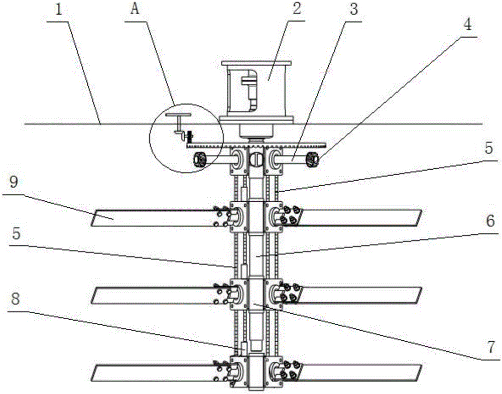
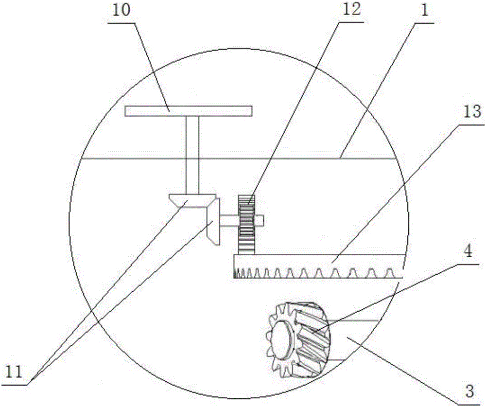
[0037] Such as figure 1 and figure 2 Shown: a pitch mixer for an asphalt tank, including a power output system placed outside the asphalt tank 1, a rotary mixing system and a pitch system placed inside the asphalt tank 1. The power output system is composed of a motor and a reducer, and the motor and the reducer are connected through a coupling. The rotary mixing system consists of a vertically arranged main shaft 6 and paddles 9 vertically fixed on the main shaft 6. The reducer is placed on the top of the asphalt tank 1 through the reducer base 2. The reducer and the main shaft 6 are connected by another coupling . Pitch change system is made up of adjusting hand wheel 10, adjusting gear set 11, rack 12, large gear plate 13, pinion 4, short shaft 3, fixed seat 7, sprocket wheel and chain 5.

[0038]In the pitch control system, the adjusting handwheel 10 is placed outside the asphalt tank 1, and the asphalt tank 1 is provided with a stop buckle for the adjusting handwheel ...


PUM


Abstract

The invention discloses an asphalt tank pitch-variable stirrer. The asphalt tank pitch-variable stirrer comprises a power output system arranged outside an asphalt tank and a rotary stirring system arranged in the asphalt tank. The power output system is mainly composed of a motor and a speed reducer connected with the motor through a coupling. The rotary stirring system is mainly composed of a vertically arranged spindle and blades perpendicularly fixed to the spindle. The speed reducer is connected with the spindle through another coupling. The stirrer further comprises a pitch variable system. The pitch variable system is composed of an adjusting hand wheel, an adjusting gear set, a rack, a big gear plate, a small gear, a short shaft, a fixing base, a chain wheel and a chain. According to the stirrer, the mounting angle of the blades of the stirrer can be adjusted in real time according to the temperature, density and viscosity changes of asphalt in the tank, effective stirring of asphalt with different temperatures, densities and viscosities can be achieved, the production efficiency of the asphalt can be effectively improved, the energy consumption is reduced, the equipment damage probability is lowered, and the asphalt tank pitch-variable stirrer has prominent practicability and remarkable economic value.

Description

technical field [0001] The invention relates to a stirrer arranged in an asphalt tank for mixing asphalt, in particular to a stirrer capable of adjusting the blade angle outside the asphalt tank according to actual needs, and belongs to the technical field of asphalt mixing equipment. Background technique [0002] In the asphalt industry, the asphalt mixer plays a very important role. If the mixer can be used effectively, it can save energy and improve the efficiency of asphalt production. For example: adding stirring to the heating of base asphalt can reduce the heating time by about 70% and reduce the heat demand for asphalt heating; while adding stirring to the development of modified asphalt can reduce the development time from 8 hours to 2 hours ~3 hours. [0003] At present, the working media used by the mixers used in the asphalt industry are almost all relatively stable mixtures, such as dust, ore, mixed liquid, etc. The density and viscosity of these substances are...

Claims


Application Information

Patent Timeline
IPC IPC(8): B01F7/18
CPCB01F27/0541B01F27/074B01F27/191B01F27/90B01F2101/38
Inventor 王维柱杨海峰
Owner 湖北安捷路桥技术有限公司
Learn More