Fiber cut-off device

A cutting device and fiber technology, applied in the direction of textiles and papermaking, metal processing, textile material cutting, etc., can solve the problems of limited contact area, time-consuming and labor-intensive cutting process, etc., and achieve the effect of increasing the contact area and approaching the length

Inactive Publication Date: 2017-04-26
TAICANG DATANG CHEM FIBER FACTORY
View PDF12 Cites 0 Cited by
  • Summary
  • Abstract
  • Description
  • Claims
  • Application Information

AI Technical Summary

Problems solved by technology

In the process of use, scissors cut due to the limited contact area between the blade of the scissors and the fiber, and the cutting process is time-consuming and laborious; in the industrial production process, cutt...

Method used


Image

  • Fiber cut-off device
  • Fiber cut-off device
  • Fiber cut-off device

Examples


Embodiment 1

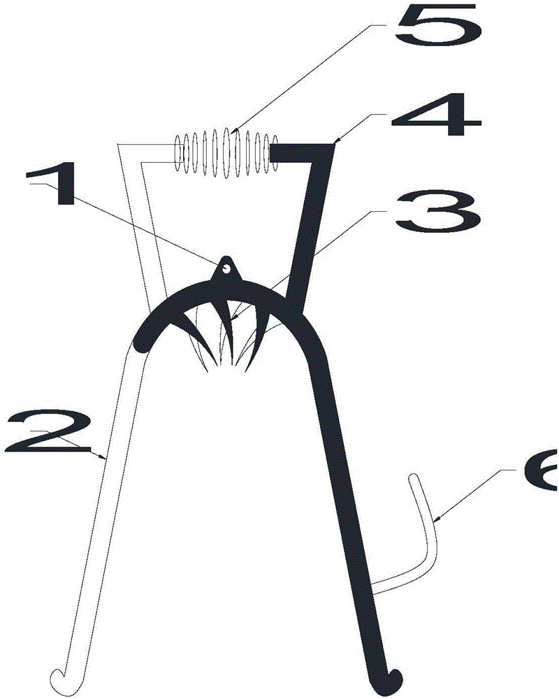
[0024] Embodiment one, see figure 1 , a fiber cutting device, comprising two shear bodies and a connector 1, characterized in that: the shear body includes a shear handle 2 and a shear joint part, the shear joint part is arc-shaped, and the inside of the shear joint part is provided with A plurality of scissors 3, the scissors 3 are provided with a cutting edge, the outer side of the scissor part is provided with a shaft hole, and the scissor handle 2 is arranged on the inner side of the scissors. When in use, the scissors 3 are inserted into the fiber tuft, and then the scissor handle 2 is pressed together to cut off the fiber tuft.

[0025] As a further improvement of the above solution, a support rod 4 is provided on the outside of the scissors, and a spring 5 is provided between the support rods 4 . The scissor handle 2 can be automatically restored to the state of preparation before cutting, which increases ease of use and saves operating time.

[0026] As a further imp...

Embodiment 2

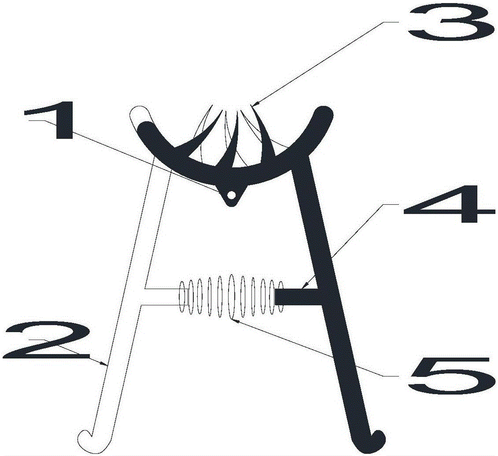
[0031] Embodiment two, see figure 2 , a fiber cutting device, comprising two shear bodies and a connector 1, characterized in that: the shear body includes a shear handle 2 and a shear joint part, the shear joint part is arc-shaped, and the inside of the shear joint part is provided with A plurality of scissors 3, the scissors 3 are provided with a cutting edge, the outer side of the shearing part is provided with a shaft hole, and the scissor handle 2 is arranged on the outer side of the shearing part. When in use, the scissors 3 are inserted into the fiber tuft, and then the scissor handle 2 is pressed together to cut off the fiber tuft.

[0032] As a further improvement of the above solution, a support rod 4 is provided on the outside of the scissors, and a spring 5 is provided between the support rods 4 . The scissor handle 2 can be automatically restored to the state of preparation before cutting, which increases ease of use and saves operating time.

[0033] As a furt...

Embodiment 3

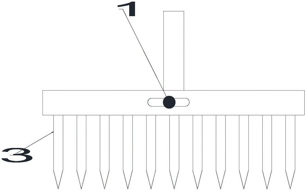
[0038] Embodiment three, refer to Figure 3-4 , a fiber cutting device, including a cutting body and a connecting piece 1, characterized in that: the two cutting bodies are used in combination, the cutting body includes a shearing handle 2 and a cutting part, and a groove 7 is provided on one side of the cutting part And convex key 8, described cutting body is provided with bar-shaped hole 9, and described connector 1 passes through bar-shaped hole 9 and connects two cutting bodies, and the lower part of described shearing part is provided with scissors 3, and described scissors 3 There are cutting edges on the left and right sides. This device can be used on large equipment. When in use, the shearing teeth 3 of the two shears are combined one by one, and then the fiber clusters are inserted. Move to the wrong direction, return to the original state, complete the second cutting, and then repeat the above steps.


PUM


Abstract

The invention provides a fiber cut-off device. The fiber cut-off device comprises two shear bodies and a connecting piece. The fiber cut-off device is characterized in that each of the shear bodies comprises a shear handle and a shearing portion which is arc-shaped; a plurality of shearing teeth are arranged on the inner side of the shearing portion, cutting edges are arranged on the shearing teeth, a shaft hole is formed in the outer side of the shearing portion, and the shear handle is arranged on the inner side of the shearing portion. During use, the shearing teeth are inserted into a fiber cluster, and then the shear handle is pressed to perform a cut-off operation of the fiber cluster. By arranging the shearing teeth to increase the contact areas of the cutting edges of the cutting device and the fibers, the fibers are more time- and labor-saving to shear, and the sheared fiber clusters are closer in length.

Description

technical field [0001] The invention relates to a cutting device, in particular to a fiber cutting device. Background technique [0002] Fiber refers to a substance consisting of continuous or discontinuous filaments. In animals and plants, fibers play an important role in maintaining tissues. Fibers are widely used and can be woven into thin threads, thread ends and hemp ropes, and can also be woven into fiber layers when making paper or felt. They are also commonly used to make other materials and form composite materials with other materials. [0003] Fiber clusters often need to be cut during use to meet the needs of different working surfaces. The prior art adopts the method of cutting or scissors cutting. In the process of use, scissors cut due to the limited contact area between the blade of the scissors and the fiber, and the cutting process is time-consuming and laborious; in the industrial production process, cutting with a guillotine knife, because the fiber cl...

Claims


Application Information

Patent Timeline
IPC IPC(8): B26B13/06B26B13/16D06H7/00
CPCB26B13/06B26B13/16D06H7/00
Inventor 刘惠峰
Owner TAICANG DATANG CHEM FIBER FACTORY
Why Eureka
Try Eureka