
Novel perforating machine

A punching machine, a new type of technology, applied in the direction of metal processing, etc., can solve the problems that the tool cannot be replaced, the gasket cannot be moved, the structure is unreasonable, etc., and achieve the effect of convenient chip removal, simple structure and extended service life

Inactive Publication Date: 2017-04-26
唐贵凤
View PDF0 Cites 0 Cited by
  • Summary
  • Abstract
  • Description
  • Claims
  • Application Information

AI Technical Summary

Problems solved by technology

In the prior art, there are various structures of the punching machine, and the structure of the punching machine is unreasonable, but paper scraps are filled into the base after punching, and it is inconvenient to take it out. There is a gasket at the position corresponding to the cutter head, but the gasket cannot be moved and is easily damaged. At the same time, the existing punching machine cannot change the cutter and can only punch a single hole, which is very inconvenient

Method used


Image

  • Novel perforating machine
  • Novel perforating machine
  • Novel perforating machine

Examples


Embodiment Construction

[0022] The present invention will be further described below in conjunction with the accompanying drawings and embodiments.

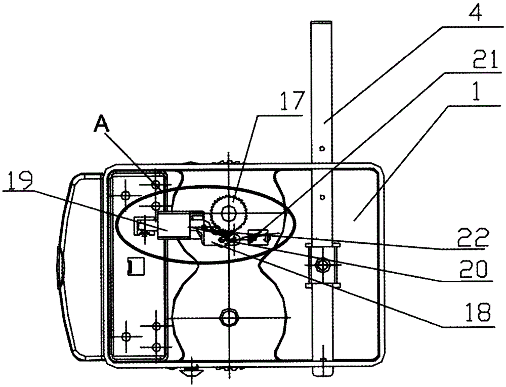
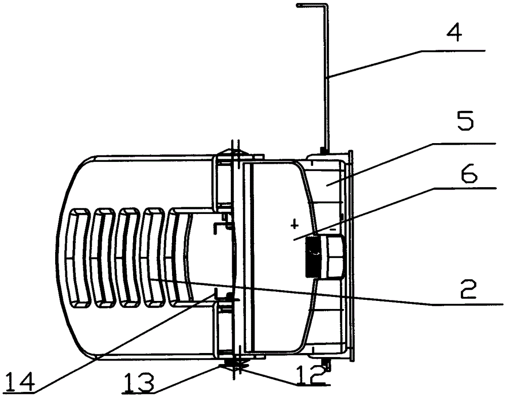
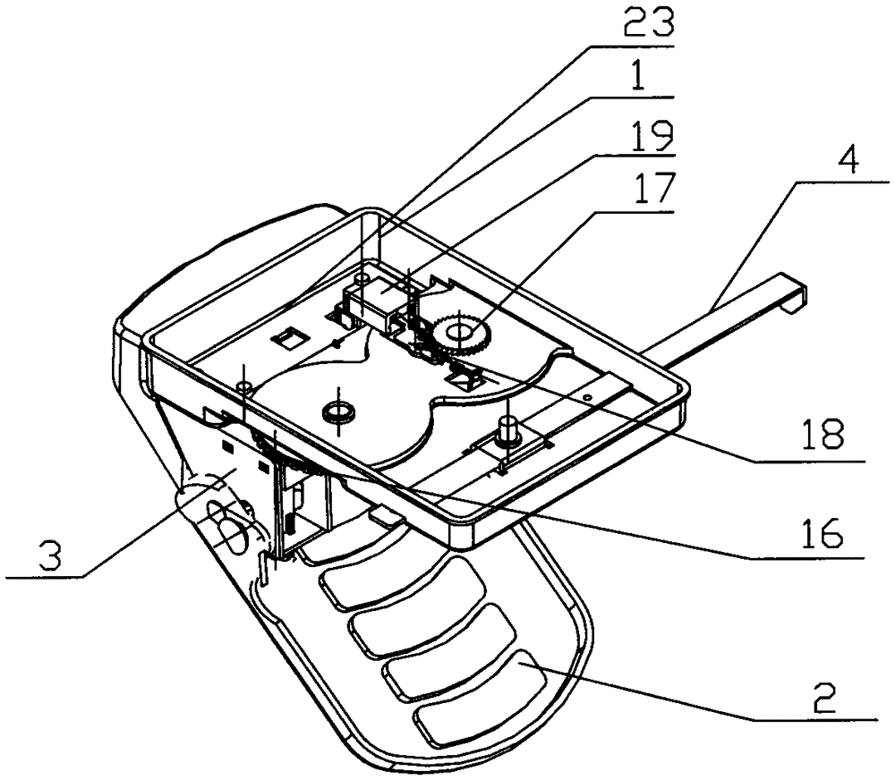
[0023] Embodiments of the present invention refer to Figure 1 to Figure 7 As shown, a new type of punching machine is mainly composed of a base 1, a handle 2, a cutter, a scale rod 4, a scrap box 5, a scrap box cover 6, a bracket 3 and a compression spring 10. The bracket 3 is divided into left and right sides. , the right two brackets, the bracket 3 is connected to the base 1 through bolts and backing plates 23, the handle 2 is connected to the bracket 3 through a short pin shaft, and the short pin shaft connecting the handle 2 and the bracket 2 is externally connected There is a clip spring 10, and the scale rod 4 is plugged into the upper front end of the base 1, and the middle position of the base 1 where the scale rod is inserted is provided with a scale rod top bead, and the scale rod 4 is provided with a ball corresponding to the scale rod top b...


PUM


Abstract

The invention discloses a novel perforating machine which comprises a base, a handle, tools, a scaleplate rod, a paper scrap box, a paper scrap box cap, brackets and a compressed spring. Tool bits are embedded into tool handles. The two tools are mounted in the left bracket and the right bracket of the perforating machine through guide blocks. The tool handles of the tools are provided with transverse through holes. The tool mounted on the left bracket is connected with the left bracket and the handle through a long pin shaft, and the tool mounted on the right bracket is connected with the right bracket and the handle through a lockset. Clamping springs are mounted on one ends of the long pin shaft and the lockset and provided with handle parts. A left gear and a right gear are mounted on the portions, under the tools, of the base of the perforating machine and driven by a rotating mechanism to rotate. A bottom cap is mounted at the lower end of the base. The novel perforating machine is simple in structure and flexible and convenient to operate, and the rotating mechanism is mounted, so that the perforating machine is durable, and the service life of the perforating machine is greatly prolonged; and by adoption of the clamping springs with the handle parts, the tools of the perforating machine are convenient to dismount and mount and flexible to replace, and scrap taking is convenient.

Description

technical field [0001] The invention relates to the field of office appliances, in particular to a novel hole punching machine which is convenient for changing knives and durable. Background technique [0002] A punching machine is a device used for punching and binding paper items such as loose-leaf pages. At present, the common punching machine is mainly composed of handle, punching knife, compression spring, and base. There are punching holes on the base. The handle is hinged with the frame base through the pin shaft. On the top of the hole, the knife head corresponds to the punching hole one by one, press the handle to rotate around the pin shaft and press down on the knife head to achieve the purpose of punching paper items. In the prior art, there are various structures of the punching machine, and the structure of the punching machine is unreasonable, but paper scraps are filled into the base after punching, and it is inconvenient to take it out. The position corres...

Claims


Application Information

Patent Timeline
Patent Type & Authority Applications(China)
IPC IPC(8): B26F1/02B26D5/10
Inventor 唐贵凤
Owner 唐贵凤
Learn More