
Driving system for electric vehicle and electric vehicle driving method

A technology of electric vehicles and driving systems, applied in the field of driving systems and electric vehicles, can solve problems such as wheel slippage, technical difficulty, and large power consumption, and achieve the effect of improving efficiency

Inactive Publication Date: 2017-04-26
山西吉利汽车部件有限公司 +1
View PDF4 Cites 7 Cited by
  • Summary
  • Abstract
  • Description
  • Claims
  • Application Information

AI Technical Summary

Problems solved by technology

For example, in the case of using a single motor to drive an electric vehicle, usually a single motor is used to drive the two front wheels at the front end of the electric vehicle or to drive the two rear wheels at the rear end of the electric vehicle; however, such electric vehicles drive on roads with a low coefficient of adhesion When this type of electric vehicle brakes, it can only recycle the braking energy of two wheels, resulting in Low braking energy recovery; especially when the motor fails, it will cause the electric vehicle to be unable to drive
For the situation where four in-wheel motors are used to drive an electric vehicle, since the in-wheel motors are directly installed in the wheels, the in-wheel motors cannot have a higher driving power due to the limited layout space of the wheels (the greater the driving power, the larger the volume of the motor ), even if the four hub motors drive the electric vehicle at the same time, the electric vehicle cannot obtain a higher speed; and the cost of arranging four hub motors is high, and the technical difficulty of the arrangement is relatively large

Method used


Image

  • Driving system for electric vehicle and electric vehicle driving method
  • Driving system for electric vehicle and electric vehicle driving method

Examples


Embodiment Construction

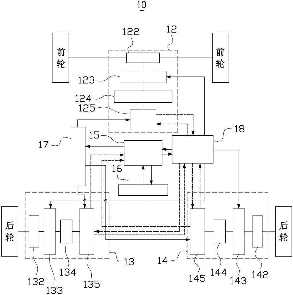
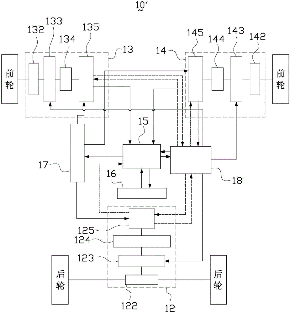
[0027] In order to further explain the technical means and effects of the present invention to achieve the intended purpose of the invention, below in conjunction with the accompanying drawings and preferred embodiments, the specific implementation of the drive system of the electric vehicle and the driving method of the electric vehicle proposed according to the present invention , structure, feature and effect thereof, be described in detail as follows:

[0028]The aforementioned and other technical contents, features and effects of the present invention will be clearly presented in the following detailed description of preferred embodiments with reference to the drawings. Through the description of specific implementation methods, the technical means and effects of the present invention to achieve the intended purpose can be understood more deeply and specifically, but the attached drawings are only for reference and description, and are not used to explain the present inven...


PUM


Abstract

A driving system for an electric vehicle comprises a first driving unit, a second driving unit, a third driving unit and a vehicle control unit, wherein the first driving unit comprises a first motor controller, which is used for controlling a permanent magnet motor to start up or shut down, and the permanent magnet motor, which is used for driving two wheels to rotate; the second driving unit comprises a second motor controller, which is used for controlling a first hub motor to start up or shut down, and the first hub motor, which is used for driving the wheels to rotate; the third driving unit comprises a third motor controller, which is used for controlling the second hub motor to start up or shut down, and the second hub motor, which is used for driving the wheels to rotate; the vehicle control unit is used for calculating slip rates; and when the slip rates of the two wheels is not less than a preset value, the vehicle control unit transmits a control signal, which is used for controlling the permanent magnet motor to shut down and controlling the hub motors to start up, so as to shut down the permanent magnet motor and start up the first hub motor and the second hub motor. Large amounts of electric power can be prevented from being consumed. The invention further relates to a driving method for the electric vehicle.

Description

technical field [0001] The invention relates to the technical field of electric vehicles, in particular to a driving system and a driving method of the electric vehicle. Background technique [0002] In recent years, with the advocacy of low-carbon and environmentally friendly life and the increasingly serious energy crisis, electric vehicles have been vigorously developed due to their advantages of zero emissions, high efficiency, and low noise. The driving mode of electric vehicles is the main force in the field of electric vehicles. One of the research contents. [0003] At present, the driving methods of electric vehicles mainly include single motor drive and four hub motor drive. For example, in the case of using a single motor to drive an electric vehicle, usually a single motor is used to drive the two front wheels at the front end of the electric vehicle or to drive the two rear wheels at the rear end of the electric vehicle; however, such electric vehicles drive on...

Claims


Application Information

Patent Timeline
Patent Type & Authority Applications(China)
IPC IPC(8): B60L11/18B60L7/14B60L7/16
CPCB60L7/14B60L7/16B60L50/51B60L58/13B60L2220/42B60L2220/44B60L2240/429Y02T10/70
Inventor 郭保军牛彦文李元旗王镫标赵博
Owner 山西吉利汽车部件有限公司
Learn More