Automatic clearing method for water body floating objects at hydraulic sluice

An automatic cleaning and floating debris technology, which is applied in the cleaning of open water, water conservancy projects, construction, etc., can solve the problems of high cost, high risk, and full cleaning speed of salvage ships, and achieve the effect of convenient and fast operation

Active Publication Date: 2017-04-26
临沂高新自来水有限公司
View PDF5 Cites 5 Cited by
  • Summary
  • Abstract
  • Description
  • Claims
  • Application Information

AI Technical Summary

Problems solved by technology

[0005] At present, salvage ships are mainly used for floating objects in the reservoir area

Method used


Image

  • Automatic clearing method for water body floating objects at hydraulic sluice
  • Automatic clearing method for water body floating objects at hydraulic sluice
  • Automatic clearing method for water body floating objects at hydraulic sluice

Examples


Embodiment 1

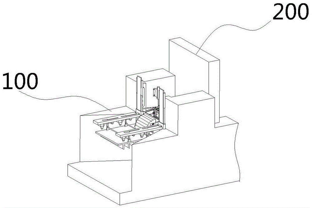
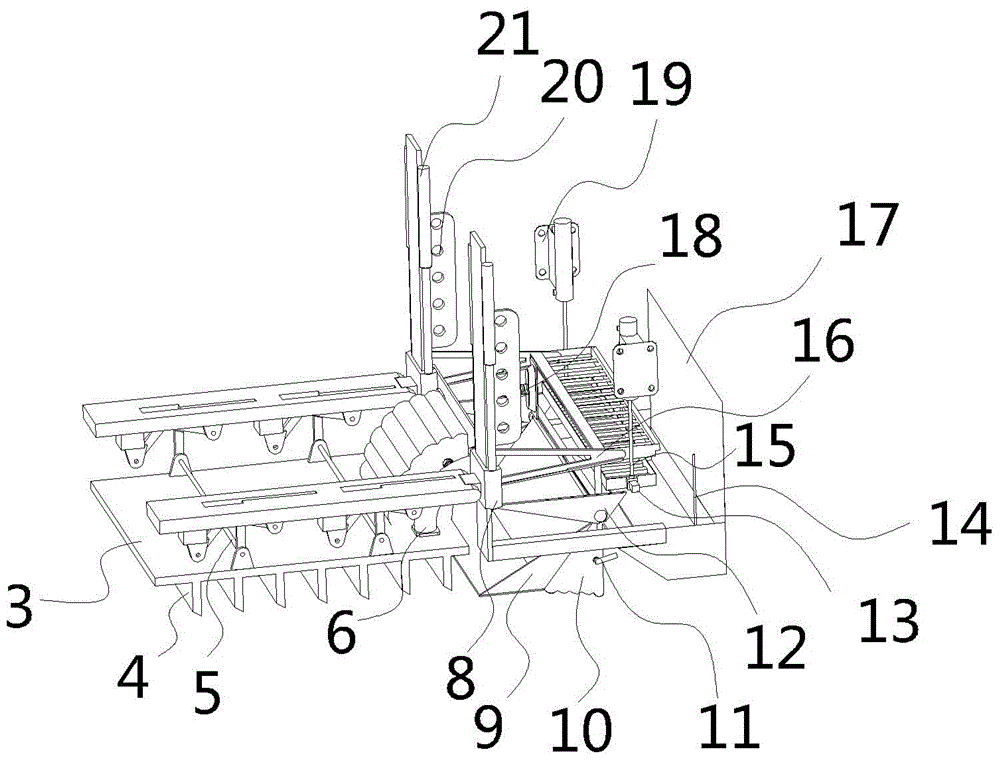
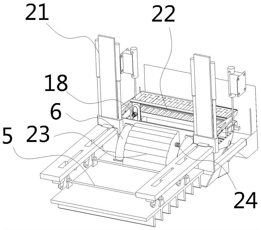
[0030] As shown in the figure, the automatic cleaning device for floating objects in the water body at the water conservancy sluice includes a dam body 100, the dam body 100 is equipped with a sluice 100, and a fixed bracket 20 is arranged symmetrically in front of the sluice 100, and then the dam body 100 is installed. Above, the fixed bracket 20 is equipped with a slider 8 driven by a hydraulic cylinder 21 to move up and down, and a horizontal plate is connected between the sliders 8; a fixed plate 27 is hinged on the slider 8 . The hydraulic cylinder one 21 lifts the slide block 8 when the device is not in use, and the fixed plate 27 is also in a parallel state with the fixed bracket one 20 when the device is not in use, so that the stepping mechanism is separated from the water surface, preventing the equipment from being soaked for a long time. damage.

[0031] The active rod 26 driven by the motor to rotate is installed on the fixed plate 27; one end of the passive rod 2...


PUM


Abstract

The invention discloses an automatic clearing method for water body floating objects at a hydraulic sluice. The automatic clearing method comprises the following steps of: mounting a device on a dam body while a fan-shaped gasbag I (23) is free of gas pressure therein, a spring (6) is in a contraction state, a fixed plate (27), a lower flat plate (3) and a fixed bracket I (20) are in a parallel state; 2) connecting an inflating and deflating valve I (24) to an inflating pump which is turned on to start to inflate the fan-shaped gasbag I (23), wherein when the fan-shaped gasbag I (23) is inflated by gas pressure, the fan-shaped gasbag I (23) is expanded in a fan shape to drive the fixed plate (27) and the lower flat plate (3) to rotate along a hinged part until the fixed plate (27), the lower flat plate (3) and the fixed bracket I (20) are in a perpendicular state. The automatic clearing method has the beneficial effects that: manual salvage is not needed, the water body floating objects at the hydraulic sluice are automatically cleared in a mechanically-driven mode, speed is high, operation is convenient, and the automatic clearing method is suitable for being popularized and used.

Description

technical field [0001] The invention relates to an automatic cleaning device for floating objects in a water body at a water conservancy sluice and a cleaning method thereof, belonging to the technical field of water conservancy engineering. Background technique [0002] With the sustained and rapid growth of my country's economy, hydropower reservoirs and infrastructure continue to expand, and people's living standards continue to improve. Therefore, the ensuing environmental pollution problem is also becoming more and more serious, especially in the field of river systems. In addition to the downstream and ecological balance being endangered, the domestic garbage floating on the water surface and wastes such as branches, bamboo and wood have a great impact on the environment of the reservoir area and the environment. The influence of hydropower stations is also increasing. At present, drift blocking and rowing have been used in some reservoir areas and power station reserv...

Claims


Application Information

Patent Timeline
IPC IPC(8): E02B15/10
CPCE02B15/10
Inventor 金宇龙
Owner 临沂高新自来水有限公司
Why Eureka
Try Eureka