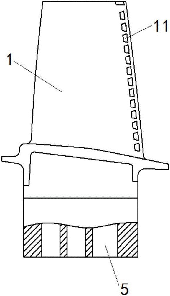
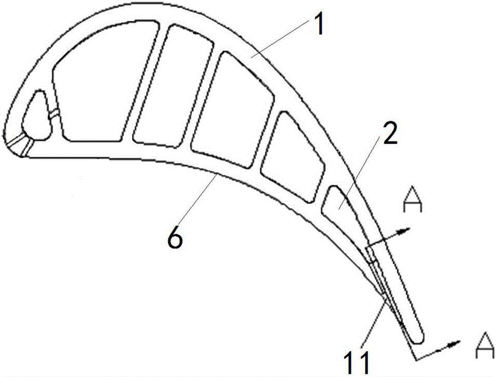
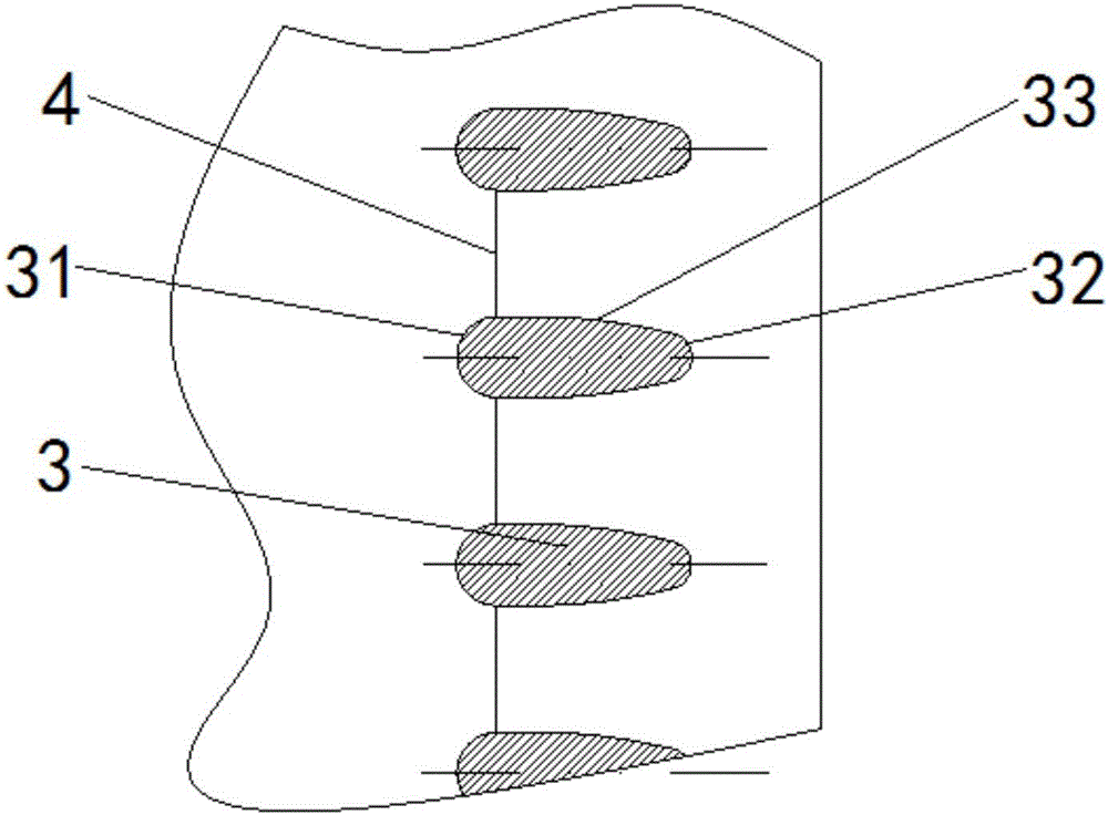
Tail edge cooling structure of turbine rotor blade and engine with tail edge cooling structure

A turbine rotor and cooling structure technology, applied in the direction of engine components, machines/engines, blade support components, etc., to achieve the effects of reducing strength, enhancing coverage, and improving cooling effect

Inactive Publication Date: 2017-04-26
AECC SHENYANG ENGINE RES INST
View PDF3 Cites 10 Cited by
  • Summary
  • Abstract
  • Description
  • Claims
  • Application Information

AI Technical Summary

Problems solved by technology

[0006] The object of the present invention is to provide a trailing edge cooling structure of a turbine rotor blade and an engine with it, so as to solve or at least alleviate at least one problem existing in the background art

Method used


Image

  • Tail edge cooling structure of turbine rotor blade and engine with tail edge cooling structure
  • Tail edge cooling structure of turbine rotor blade and engine with tail edge cooling structure
  • Tail edge cooling structure of turbine rotor blade and engine with tail edge cooling structure

Examples


Embodiment Construction

[0022] In order to make the objectives, technical solutions and advantages of the present invention clearer, the technical solutions in the embodiments of the present invention will be described in more detail below in conjunction with the drawings in the embodiments of the present invention. In the drawings, the same or similar reference numerals denote the same or similar elements or elements having the same or similar functions throughout. The described embodiments are some, but not all, embodiments of the invention. The embodiments described below by referring to the figures are exemplary and are intended to explain the present invention and should not be construed as limiting the present invention. Based on the embodiments of the present invention, all other embodiments obtained by persons of ordinary skill in the art without creative efforts fall within the protection scope of the present invention. Embodiments of the present invention will be described in detail below ...


PUM


Abstract

The invention discloses a tail edge cooling structure of a turbine rotor blade and an engine with the tail edge cooling structure, and relates to the technical field of engines. According to the tail edge cooling structure of the turbine rotor blade, the tail edge of the blade is provided with a plurality of mutually independent expansion type cooling split gaps in the height direction of the blade; and the opening widths of the expansion type cooling split gaps in the height direction of the blade are gradually expanded along a direction from an inner cavity of the blade to the outer surface of the blade. The rotor blade on the engine comprises the tail edge cooling structure of the turbine rotor blade. The tail edge cooling structure has the advantages that as the multiple mutually independent expansion type cooling split gaps are formed in the tail edge of the blade in the height direction of the blade, on one hand, the expansion type split gaps enlarge the covering area of cold air, and on the other hand, gradual expansion replaces sudden expansion, thus reducing the intensity of a vortex at a cold air outlet and attenuating the degree of cold air separation due to extrusion of the vortex; and therefore, coverage of the cold air can be enhanced, the cooling effect is improved, and the wall surface temperature of the tail edge of the blade is reduced.

Description

technical field [0001] The invention relates to the technical field of engines, in particular to a trailing edge cooling structure of turbine rotor blades and an engine with the same. Background technique [0002] At present, the gas temperature of a gas turbine engine has reached above 1800K, which is far higher than the melting temperature of the base metal of the turbine rotor blade. Usually, it is necessary to extract high-pressure air from the compressor as cold air, and use its lower temperature to cool the The blades are cooled to reduce the wall temperature. The blades are generally designed as a hollow structure, and multiple cooling channels are arranged in the inner cavity. According to the difference in heat transfer intensity in different areas of the outer wall surface of the blade and the gas contact, different enhanced cooling measures are taken, and different cooling structures are used in a targeted manner. The blade is cooled to ensure that the temperatur...

Claims


Application Information

Patent Timeline
Patent Type & Authority Applications(China)
IPC IPC(8): F01D5/18
CPCF01D5/187
Inventor 黎旭王焘
Owner AECC SHENYANG ENGINE RES INST
Why Eureka
Try Eureka