
Method and system for online monitoring state of fiber-optical current transducer and self-diagnosis

A technology of optical fiber current and transformer, which is applied in the direction of instruments, measuring devices, measuring electrical variables, etc., can solve problems such as the inability to directly monitor the output optical power of the light source, the inability to realize the self-diagnosis of the working status of the light source, and the inability to achieve online monitoring of products, etc. Achieve the effect of improving convenience, improving stability and improving reliability

Inactive Publication Date: 2017-04-26
CHINA ELECTRIC POWER RES INST +3
View PDF6 Cites 15 Cited by
  • Summary
  • Abstract
  • Description
  • Claims
  • Application Information

AI Technical Summary

Problems solved by technology

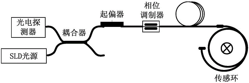
[0004] Most of the existing on-line monitoring methods for optical fiber current transformers monitor the loss of the entire optical path by monitoring the total optical power received by the photodetector, which includes the loss of other optical devices and optical path fusion points, and cannot directly monitor the loss of the light source. output optical power, and it is impossible to realize the self-diagnosis of the working state of the light source
As for the monitoring of the central wavelength of the light source spectrum, currently only spectrometers can be used in the laboratory for testing, and online monitoring during the on-site operation of the product cannot be achieved.

Method used


Image

  • Method and system for online monitoring state of fiber-optical current transducer and self-diagnosis
  • Method and system for online monitoring state of fiber-optical current transducer and self-diagnosis
  • Method and system for online monitoring state of fiber-optical current transducer and self-diagnosis

Examples


Embodiment Construction

[0035] Exemplary embodiments of the present invention will now be described with reference to the drawings; however, the present invention may be embodied in many different forms and are not limited to the embodiments described herein, which are provided for the purpose of exhaustively and completely disclosing the present invention. invention and fully convey the scope of the invention to those skilled in the art. The terms used in the exemplary embodiments shown in the drawings do not limit the present invention. In the figures, the same units / elements are given the same reference numerals.

[0036] Unless otherwise specified, the terms (including scientific and technical terms) used herein have the commonly understood meanings to those skilled in the art. In addition, it can be understood that terms defined by commonly used dictionaries should be understood to have consistent meanings in the context of their related fields, and should not be understood as idealized or over...


PUM


Abstract

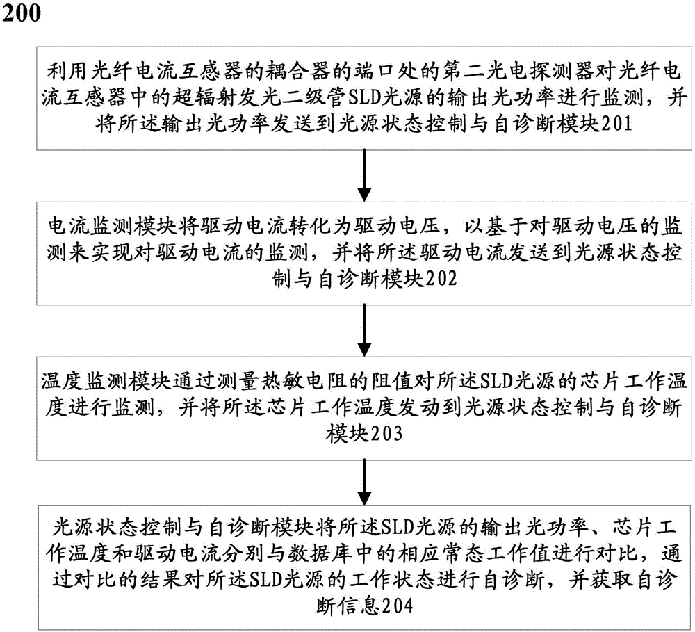
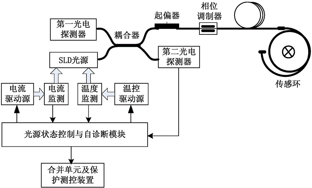
The invention discloses a method for online monitoring the state of a fiber-optical current transducer and conducting self-diagnosis. The method includes the following steps: using a second photoelectronic detector which is arranged at a port of a coupler of the fiber-optical current transducer to monitor the output light power of a superluminescent light-emitting diode (SLD) light source in the fiber-optical current transducer and transmit the output light power to a light source state control and self-diagnosis module; a current monitoring module monitoring drive current and transmitting the drive current to the light source state control and self-diagnosis module; a temperature monitoring module monitoring the working temperature of a chip of the SLD light source by measuring the resistance of a thermistor and transmitting the working temperature of the chip to the light source state control and self-diagnosis module; the light source state control and self-diagnosis module separately comparing the output light power of the SLD light source, the working temperature of the chip and the drive current with corresponding normal state working values in a database, and conducting self-diagnosis on the working state of the SLD light source on the basis of the result of the comparison, and acquiring self-diagnosis information.

Description

technical field [0001] The present invention relates to the technical field of on-line monitoring and self-diagnosis of the working state of an optical fiber current transformer used in a smart grid, and more particularly relates to an online state monitoring and self-diagnosis method and system of an optical fiber current transformer. Background technique [0002] Optical fiber current transformers will be affected by various factors during the on-site operation of substations, such as external factors, including: ambient temperature, vibration, shock and electromagnetic interference, etc.; internal factors include: optoelectronic device performance aging, optical path loss increase etc. These factors will cause changes in the internal working state of the fiber optic current transformer, thereby reducing the accuracy and reliability of the product. [0003] At present, the light source used in fiber optic current transformers is a superluminescent light-emitting diode (SLD...

Claims


Application Information

Patent Timeline
Patent Type & Authority Applications(China)
IPC IPC(8): G01R35/02
CPCG01R35/02
Inventor 胡蓓叶国雄肖浩徐珂黄华刘翔王洋刘博阳熊俊军万罡冯翔翔牧晓菁刘宏领王维令韩燕飞谷栋王震彭顺李建光雷军
Owner CHINA ELECTRIC POWER RES INST
Learn More