An optical power monitoring system

An optical power monitoring and power monitoring technology, applied in photometry, signal transmission system, optical radiation measurement, etc., can solve the problems of small dynamic range, poor accuracy, and difficulty in amplitude modulation control of LD, and achieve good coupling effect and reliable performance. , the effect of simple structure

Inactive Publication Date: 2018-06-26
SHANDONG UNIV OF TECH +1
View PDF4 Cites 0 Cited by
  • Summary
  • Abstract
  • Description
  • Claims
  • Application Information

AI Technical Summary

Problems solved by technology

In the prior art, when the LD emits light, there are two light output surfaces. In addition to the normal front light output, the back can also receive a certain intensity of light. Using this feature, there are devices on the market that can monitor the power of the LD. LD, because the luminous power of LD is seriously affected by temperature, the main application of this technology design is to realize constant temperature control of LD by monitoring the luminous change of LD, but it is very difficult for this kind of LD to be used for amplitude modulation control, including The reason why LD luminescence is sensitive to temperature will lead to poor accuracy when used. More importantly, when LD is used for modulation, its dynamic range is too small, so at present, LD is more suitable for use in single-mode fiber to achieve large-capacity communication in digital mode. occasions other than AM control applications
[0007] The light-emitting mechanism of LED is different from that of LD. When it emits light, it can only emit light in one direction at a larger radiation angle. Therefore, it is still impossible to monitor the luminous power of LED in the prior art, so no matter whether it is directly controlled or indirectly controlled. Unable to achieve the desired linear relationship between the control electrical signal and the luminous power of the LED

Method used


Image

  • An optical power monitoring system
  • An optical power monitoring system
  • An optical power monitoring system

Examples


Embodiment 1

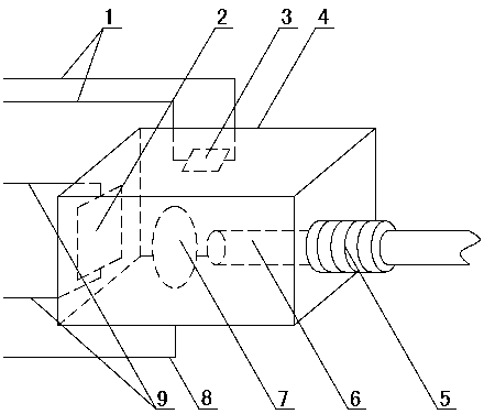
[0033] Such as figure 1 As shown, an optical device with a power monitoring function includes a housing 4, and an inner cavity is arranged in the housing 4. In this optical device with a power monitoring function, the external structure of the housing 4 can be designed into any shape as required ( Such as cylinder, rectangular body), the inner cavity is preferably set in the shape of a rectangular body. A focusing lens 7 is arranged in the cuboid-shaped inner cavity, and light-emitting diodes 2 and optical fibers 6 are respectively arranged on both sides of the focusing lens 7 . The optical fiber interface 5 can be any current interface type, such as SMA, FC, ST and other interfaces.

[0034] The light-emitting diode 2 is preferably packaged in a patch type, the light-emitting diode 2 is fixed on any side wall of the rectangular inner cavity, the optical fiber interface 5 is set on the side wall opposite to the light-emitting diode 2, and the optical fiber 6 is connected with...

Embodiment 2

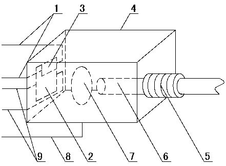
[0051] The difference between embodiment 2 and embodiment 1 is: as image 3 As shown, in this embodiment, the photodiode 3 with an area smaller than that of the light-emitting diode 2 is adopted, the photodiode 3 is not arranged on the side wall of the inner cavity of the housing 4, and the photodiode 3 is fixed on the surface of the light-emitting diode 2, Therefore, after the light-emitting diode 2 emits light, it will irradiate the photodiode 3. The part of the surface of the light-emitting diode 2 that is not blocked by the photodiode 2 is focused by the focusing lens 7 and enters the optical fiber 6 to realize the transmission of electrical signals from the high-voltage side to the low-voltage side. . Other implementations of Example 2 are the same as Example 1.


PUM


Abstract

The invention discloses an optical device with a function of power monitoring and an optical power monitoring system, and belongs to the technical field of optical communication and power measurement. The optical device comprises a housing (4) with an inner cavity; the interior of the inner cavity is fixedly provided with a light-emitting module, a power feedback module which monitors the power of the light-emitting module and generates a feedback signal, and an optical signal transmission module; the light emitted by the light-emitting module irradiates the power feedback module and the optical signal transmission module at the same time; and the housing (4) is provided with a signal input pin (9) and a signal output pin (1). According to the invention, the optical device enables the luminous power and a to-be-transmitted analog electric signal to be in linear relation through monitoring the luminous power of the light-emitting module, thereby achieving the high-precision optical fiber transmission of the analog electric signal from a high-voltage side to a low-voltage side in an analog mode.

Description

technical field [0001] An optical power monitoring system belongs to the fields of optical communication technology and electric power measurement technology. Background technique [0002] In the field of power measurement, the measured electrical quantities (such as voltage and current) are usually in a high-voltage environment. For example, the bus current to be measured by a current transformer is usually in a voltage level environment above 10kV, and the surge voltage caused by lightning can reach several hundred above kV. When measuring these quantities, in addition to converting the electrical quantity to be measured to a small signal range that the instrument can accept, it is usually necessary to keep the actual measuring instrument in a low-voltage environment. For true isolation, fiber optics must be used. Therefore, the application of optical devices to the measurement of the power field is a specific application of the field of optical communication in the fiel...

Claims


Application Information

Patent Timeline
Patent Type & Authority Patents(China)
IPC IPC(8): G01J1/42G08C23/06
CPCG01J1/4257G08C23/06
Inventor 徐丙垠王玮王敬华贾明娜王俊江
Owner SHANDONG UNIV OF TECH
Why Eureka
Try Eureka