Modulation/demodulation method capable of monitoring optical power level

A technology of modulation and demodulation and optical power, which is applied in the direction of photometry, measuring devices, and instruments using electric radiation detectors, can solve problems such as increasing costs, and achieve the effects of improving reliability, important application value, and promotion value

Inactive Publication Date: 2011-05-11
ZHEJIANG UNIV
View PDF0 Cites 0 Cited by
  • Summary
  • Abstract
  • Description
  • Claims
  • Application Information

AI Technical Summary

Problems solved by technology

without adding cost

Method used


Image

  • Modulation/demodulation method capable of monitoring optical power level
  • Modulation/demodulation method capable of monitoring optical power level
  • Modulation/demodulation method capable of monitoring optical power level

Examples


Embodiment Construction

[0029] Below in conjunction with accompanying drawing and embodiment the present invention will be further described:

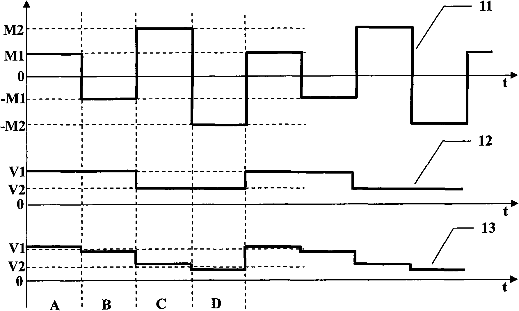
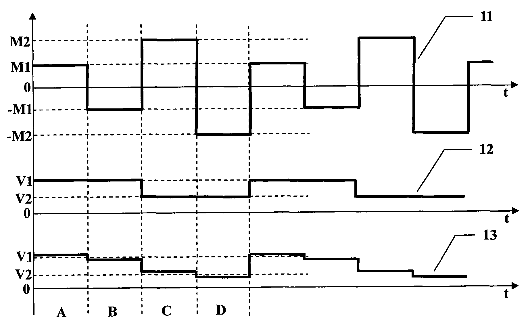
[0030] As shown in the schematic diagram of the modulation and demodulation process in the accompanying drawing, the curve 11 in the figure is a phase modulation signal. The curve 11 is different from the commonly used square wave signal, but there is a certain similarity. The phase modulation signal 11 is a periodic signal, which includes four modulation Phase, the duration of each modulation phase is the same, which is equal to the transit time of the fiber optic gyroscope, as shown in A, B, C and D in the figure, and the absolute value of the modulation phase of A and B is the same, which is M1, and the sign is opposite; The absolute values ​​of the modulation phases of C and D are the same, M2, with opposite signs, but the sizes of M1 and M2 are different, and they are not equal to an integer multiple of the π phase, so as to prevent the fiber optic gyrosc...


PUM


Abstract

The invention discloses a modulation / demodulation method capable of monitoring optical power level. The method comprises the following steps: carrying out periodic modulation on a fiber optic gyro by a phase modulating signal with specific properties, sampling corresponding output signals, and according to a preset demodulation formula, obtaining a Sagnac phase difference which is not related to the optical power and a demodulating result of the optical power in a system so as to monitor the optical power. The adopted phase modulating signal comprises an A part, a B part, a C part and a D part, wherein the absolute value of the A modulating phase and the B modulating phase is same but the symbols are opposite; and the absolute value of the C modulating phase and the D modulating phase is same but the symbols are opposite. The output signals of the fiber optic gyro under the four different modulating phases are sampled by a sampling circuit, and the Sagnac phase difference demodulatingand optical power monitoring are realized according to a known formula, so the method does not need to add or change conventional hardware; and the working condition of the fiber optic gyro is monitored in real time by the reasonable modulation / demodulation method so as to improve the reliability of the application system, and the method has high application value and popularization value.

Description

technical field [0001] The invention relates to a fiber optic gyroscope signal processing method, in particular to a modulation and demodulation method capable of monitoring optical power. Background technique [0002] Fiber optic gyroscope is a new type of angular rate measuring instrument, which is widely used in navigation and attitude control systems due to its advantages of all solid state, wide bandwidth and digital output with multiple protocols. The working principle of the fiber optic gyro is a fiber optic interferometer based on the optical Sagnac effect, that is, when the ring interferometer rotates, a Sagnac phase difference (also often called Sagnac Phase shift or Sagnac phase), by detecting the phase difference, combined with the pre-measured scale factor, the angular velocity of the system where the ring interferometer is located can be calculated, and the scale factor is usually calibrated by the turntable after the fiber optic gyroscope is manufactured. It ...

Claims


Application Information

Patent Timeline
Patent Type & Authority Patents(China)
IPC IPC(8): G01C19/66G01J1/42G01P9/00
Inventor 陈杏藩王磊薛宁周虎舒晓武刘承
Owner ZHEJIANG UNIV
Why Eureka
Try Eureka