Multi-carrier signal form-based ionosphere detection method and system

A multi-carrier signal and detection method technology, applied in the field of ionospheric detection, can solve the problems of detection distance, detection data robustness, inability to obtain ionospheric measurement parameters in time, unsuitable for multi-channel multi-band frequency detection, etc., to shorten the detection time Duty cycle, increase bandwidth, enhance the effect of function expansion

Active Publication Date: 2017-04-26
中国电波传播研究所
View PDF4 Cites 12 Cited by
  • Summary
  • Abstract
  • Description
  • Claims
  • Application Information

AI Technical Summary

Problems solved by technology

[0005] The obvious disadvantage of the detection method of the existing device is that it takes a long time to complete a periodic detection, and only one bandwidth channel can be detected in one cycle, which is not suitable for the application environment that needs to realize multi-channel multi-band detection in real time and quickly
Specifically, the long working cycle to complete a full-band detection does not fully meet the needs of full-time real-time ionospheric detection. When the ionosphere is in an unstable state, the ionospheric measurement parameters cannot be obtained i

Method used


Image

  • Multi-carrier signal form-based ionosphere detection method and system
  • Multi-carrier signal form-based ionosphere detection method and system
  • Multi-carrier signal form-based ionosphere detection method and system

Examples


Embodiment 1

[0061] Embodiment 1, this embodiment discloses an ionospheric detection method based on a multi-carrier signal form, including the following steps:

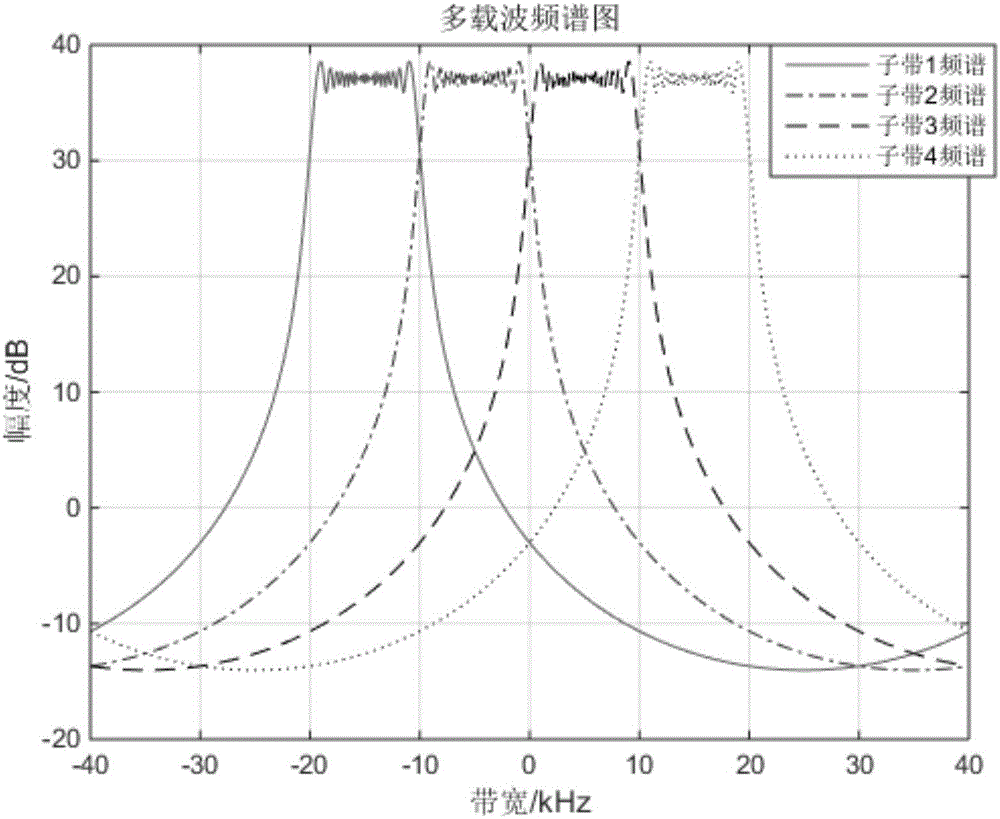
[0062] 1) Generate a multi-carrier signal according to the above formula (1), and transmit it according to the set timing.

[0063] 2) Transmit and receive synchronously for collection to obtain received signals.

[0064] 3) Matching filtering is performed on different subband combinations and the received data to obtain detection results of each subband combination.

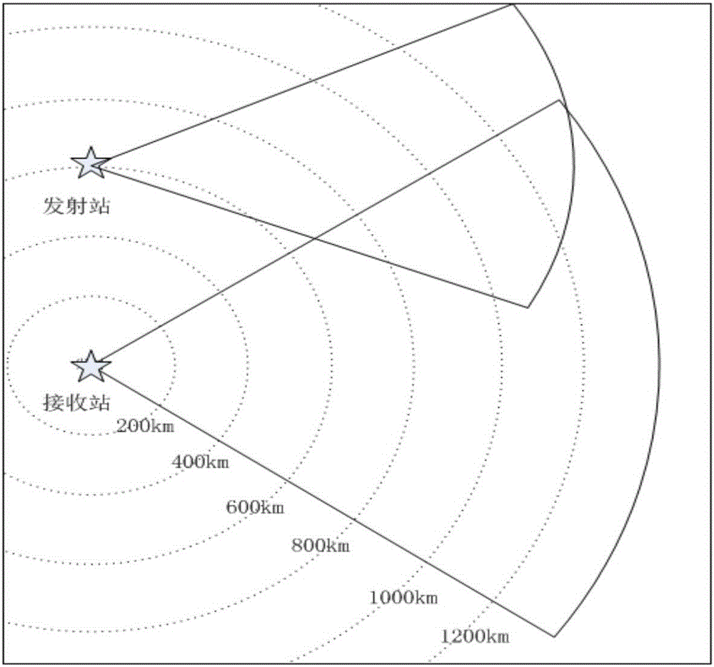
[0065] Figure 4 , Figure 5 , Image 6 , Figure 7 The side return scatter scan pattern formed for different subband combinations, where Figure 4 Sweep pattern of side return scatter formed by subband 1, i.e. 10kHz bandwidth, Figure 5 Combination of subbands 1 and 2, that is, the lateral backscatter sweep pattern formed by 20kHz bandwidth, Image 6 Combination of sub-bands 1, 2, and 3, that is, the lateral backscatter sweep pattern formed by 30kHz bandwid...


PUM


Abstract

The invention discloses a multi-carrier signal form-based ionosphere detection method and system. The method includes the following steps that: (1) at a transmitting end, the baseband data of linear frequency modulation multi-carrier signals are constructed, an orthogonal up-conversion technology is adopted to generate continuous-sweeping frequency high-frequency analog radio frequency signals, the high-frequency analog radio frequency signals are subjected to power amplification, and the power amplified high-frequency analog radio frequency signals are radiated to the space through an antenna; and (2) at a receiving end, zero-intermediate frequency baseband data are generated through a broadband receiver, high-speed sampling, digital down conversion and decimation filtering, matched filtering is performed on sub-bands, the echo data of the sub-bands are obtained, or matched filtering is performed on the sub-bands with the joint of bandwidth, and echo data under the joint of the bandwidth are obtained. The real-time performance of the ionosphere detection system is improved, a detection working period is shortened, and therefore, optimal use frequency can be obtained more accurately when an ionosphere is in an unstable state; ionosphere detection bandwidth is improved; the distance resolution of the ionosphere detection system is improved; the finer structure of the ionosphere can be obtained; and the structure state of the ionosphere can be reflected more authentically.

Description

technical field [0001] The invention relates to the field of ionospheric detection, in particular to an ionospheric detection method and system based on a multi-carrier signal form. Background technique [0002] As the radio wave propagation medium, the ionosphere has random changes in day, season and year. The structure of the ionosphere varies greatly on different spatial and temporal scales, which will largely affect its properties as a radio propagation medium. For an electromagnetic wave with a given frequency and polarization characteristics, the electromagnetic characteristics, geometric structure and time variation of the channel space medium are the propagation environment and boundary conditions of the electromagnetic wave, which determine the propagation mechanism, propagation mode and change characteristics of the electromagnetic wave. It is necessary to realize fast and real-time multi-channel detection of the ionosphere at a specific time and occasion. [000...

Claims


Application Information

Patent Timeline
IPC IPC(8): G01S7/41
CPCG01S7/41
Inventor 张曙光张成峰李强张长亮王昶朱启强李星
Owner 中国电波传播研究所
Why Eureka
Try Eureka