PET detector, PET imaging system and PET tester

A detector and photodetector technology, which is applied in the fields of PET detectors, PET imaging systems and PET inspection instruments, can solve the problems of blurred image edges and difficult identification, and achieve the advantages of reducing adverse effects, improving detection rate, and reducing use costs. Effect

Inactive Publication Date: 2017-04-26
SHENZHEN INST OF ADVANCED TECH CHINESE ACAD OF SCI
View PDF10 Cites 5 Cited by
  • Summary
  • Abstract
  • Description
  • Claims
  • Application Information

AI Technical Summary

Problems solved by technology

[0005] When the existing PET detectors use continuous scintillation crystals for imaging, the spatial resolution of the area where the continuous scintillation crystals deviate from the center of the field of view is much worse than that of the central area of ​​the field of view of the continuous scintillation crystals. The edge is blurred, difficult to identify, and the edge effect is very obvious

Method used

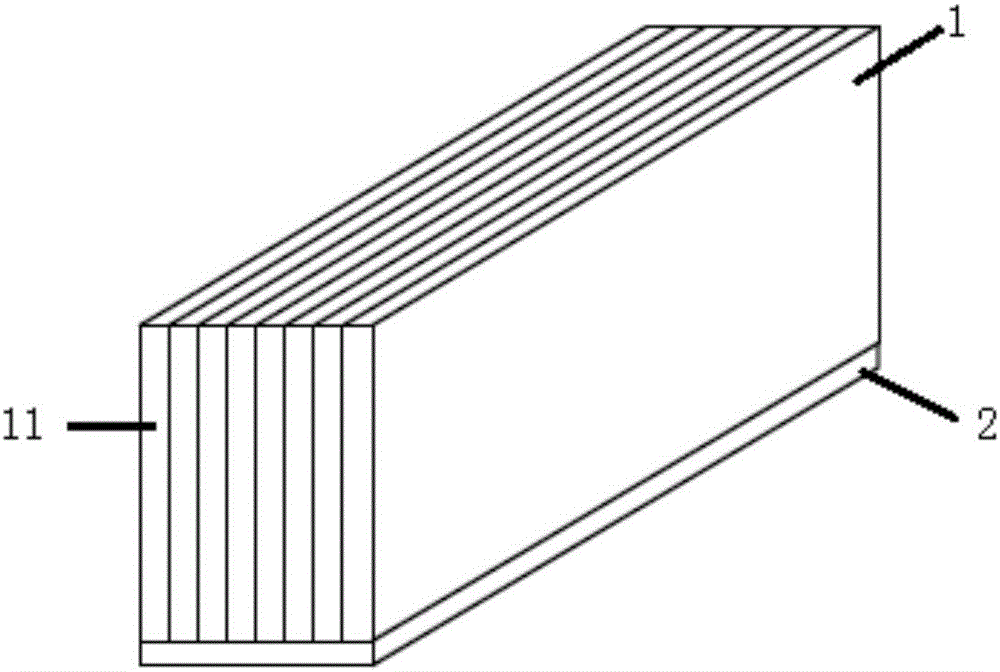
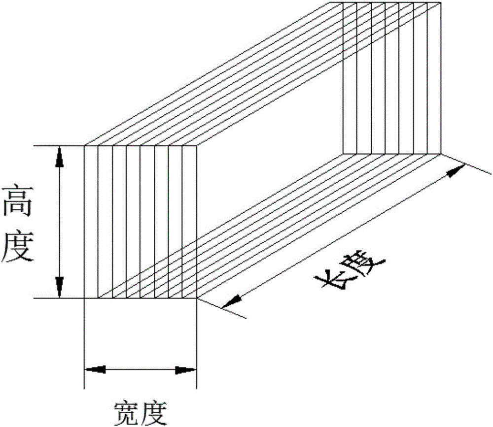
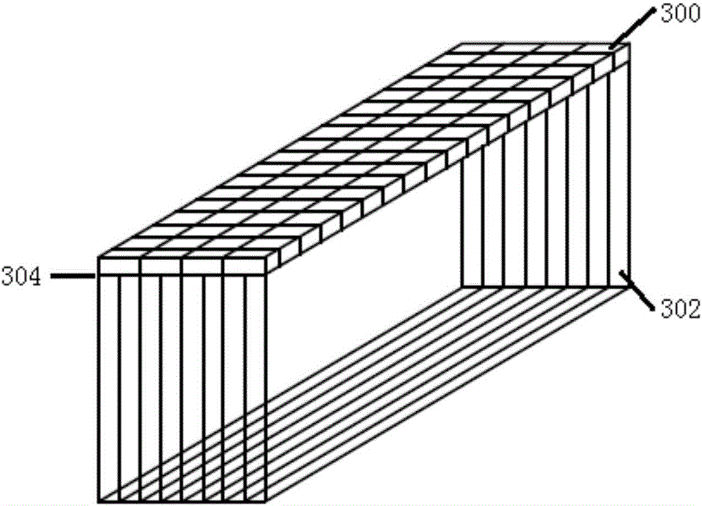

Image

  • PET detector, PET imaging system and PET tester
  • PET detector, PET imaging system and PET tester
  • PET detector, PET imaging system and PET tester

Examples


Embodiment Construction

[0028] In order to make the purpose, technical solutions and advantages of the embodiments of the present invention clearer, the technical solutions in the embodiments of the present invention will be clearly and completely described below in conjunction with the drawings in the embodiments of the present invention. Obviously, the described embodiments are only It is some embodiments of the present invention, but not all of them. The components of the embodiments of the invention generally described and illustrated in the figures herein may be arranged and designed in a variety of different configurations. Accordingly, the following detailed description of the embodiments of the invention provided in the accompanying drawings is not intended to limit the scope of the claimed invention, but merely represents selected embodiments of the invention. Based on the embodiments of the present invention, all other embodiments obtained by those skilled in the art without creative effort...


PUM


Abstract

The invention provides a PET (Positron Emission Tomography) detector, a PET imaging system and a PET tester. The PET detector comprises a semi-continuous crystal and a photoelectric detector array coupled to the semi-continuous crystal. The semi-continuous crystal is a scintillation crystal formed by coupling multiple internally uncut continuous crystal plates in the cascading order in the width direction. The semi-continuous crystal is cut into multiple continuous crystal plates in the length direction, and the multiple continuous crystal plates are coupled in the cascading order in the width direction of the semi-continuous crystal. Through the PET detector, the PET imaging system and the PET tester provided by the embodiments of the invention, full-field high spatial resolution and high efficiency can both be achieved at low cost.

Description

technical field [0001] The invention relates to the technical field of object imaging, in particular to a PET detector, a PET imaging system and a PET inspection instrument. Background technique [0002] At present, Positron Emission Tomography (PET) technology can quantitatively and non-invasively measure the changes of biomolecules labeled with positron-emitting nuclides over time in vivo, and is widely used in tumors, cardiovascular diseases and Early diagnosis of neurological diseases, etc. PET detectors are key imaging components in PET imaging systems. [0003] In the related art, the PET detector includes: a continuous scintillation crystal and two photodetector modules respectively coupled to the top surface (γ photon incident surface) and the bottom surface of the continuous crystal, so that the imaging process can be obtained through the top surface of the continuous scintillation crystal. Information such as the position, time and energy of the interaction of γ ...

Claims


Application Information

Patent Timeline
Patent Type & Authority Applications(China)
IPC IPC(8): G01T1/29
CPCG01T1/2985
Inventor 杨永峰章先鸣邝忠华王晓辉付鑫胡战利任宁梁栋刘新郑海荣
Owner SHENZHEN INST OF ADVANCED TECH CHINESE ACAD OF SCI
Why Eureka
Try Eureka