
Method for improving linearity of microwave imaging by using compressed sensing

A technology of microwave imaging and compressed sensing, applied in the fields of re-radiation, radio wave reflection/re-radiation, radio wave measurement system, etc., can solve problems such as high demand for computing resources, inability to image and compute, and large amount of computation. Achieve the effects of increasing sparsity, fast calculation, and reducing complexity

Inactive Publication Date: 2019-01-29
ZHEJIANG UNIV
View PDF5 Cites 7 Cited by
  • Summary
  • Abstract
  • Description
  • Claims
  • Application Information

AI Technical Summary

Problems solved by technology

However, the strong nonlinearity brought by the large dielectric constant makes most algorithms unable to image and calculate the target with large dielectric constant.
In addition, many current electromagnetic inverse scattering algorithms use iterative technology, which has a large amount of calculation and a high demand for computing resources, which is also a bottleneck restricting the application of electromagnetic inverse scattering technology.

Method used


Image

  • Method for improving linearity of microwave imaging by using compressed sensing
  • Method for improving linearity of microwave imaging by using compressed sensing
  • Method for improving linearity of microwave imaging by using compressed sensing

Examples


Embodiment Construction

[0030] The following describes the implementation process of the present invention in detail with reference to the accompanying drawings in the embodiments of the present invention.

[0031] The specific implementation of the present invention is:

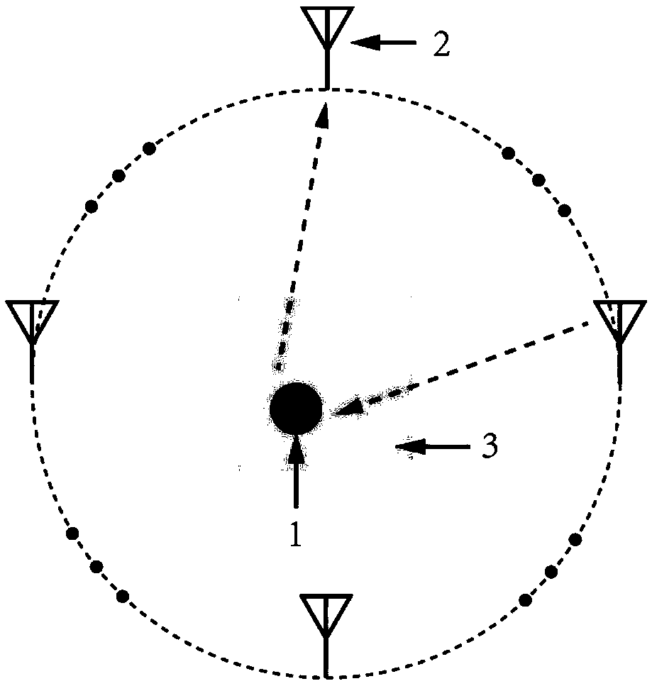
[0032] 1) Build a microwave imaging system. The microwave imaging system includes multiple transmitting and receiving antennas 2. There are multiple transmitting and receiving antennas 2 evenly spaced around the target 1 with a larger dielectric constant. One of the transmitting and receiving antennas 2 serves as The transmitting antenna emits electromagnetic waves toward the target 1 to form an incident field, and the incident field forms a scattered field around the target 1. The remaining transceiver antennas 2 serve as receiving antennas to uniformly receive the scattered field and complete the spatial uniform sampling of the signal;

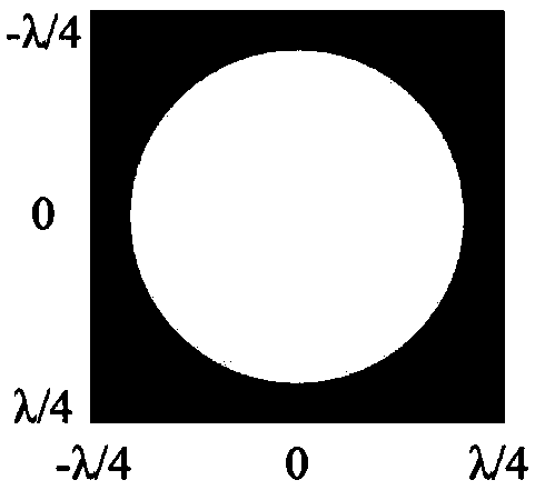
[0033] 2) Establish a preliminary imaging area 3 according to the approximate position range of the ...


PUM


Abstract

The invention discloses a method for improving the linearity of microwave imaging by using compressed sensing, which comprises the steps of setting up a microwave imaging system, wherein a plurality of transmitting and receiving antennas are uniformly distributed at intervals in a circle around a target to be measured with a large dielectric constant, one of the transmitting and receiving antennasserves as a transmitting antenna to emit electromagnetic waves to the target to be measured so as to form an incident field, the incident field forms a scattering field around the target to be measured, the rest of the transmitting and receiving antennas serve as receiving antennas to uniformly receive the scattering field; establishing a preliminary imaging area according to the approximate position range of the target to be measured, enabling the target to be measured to be located in the preliminary imaging area, increasing the space sparsity characteristics between the target to be measured and the imaging area, and carrying out processing and imaging on received scattering field signals by adopting a compressed sensing method, wherein the imaging effect is ideal along the increase inlinearity of an imaging algorithm. The method disclosed by the invention can effectively improve the nonlinearity of the traditional microwave imaging algorithm when imaging a target with a large dielectric constant, and has the characteristics of simple and convenient implementation, fast calculation and the like.

Description

Technical field [0001] The invention relates to a method for improving the performance of microwave imaging, in particular to a method for improving the linearity of microwave imaging by using compressed sensing. Background technique [0002] Microwave imaging refers to an imaging method that uses microwaves as information carriers. Its principle is to illuminate the target to be measured with electromagnetic waves in the microwave frequency band, and reconstruct the shape or permittivity distribution of the target through the measured value of the scattered field excited by the target. Microwave imaging is essentially an inverse scattering problem, which extracts target feature information based on scattered echo signals. Microwave imaging has the characteristics of safety, non-contact, and low cost, so it is widely used in military and civilian fields such as security inspections, partition surveillance, and medical imaging. [0003] Although the problem of electromagnetic inver...

Claims


Application Information

Patent Timeline
Patent Type & Authority Applications(China)
IPC IPC(8): G01S13/89
CPCG01S13/89
Inventor 周天益冉立新
Owner ZHEJIANG UNIV
Learn More