A radio frequency microelectromechanical microstrip antenna

A microstrip antenna and microcomputer technology, applied to antennas, individually powered antenna arrays, antenna coupling, etc., can solve problems such as bandwidth reduction, deterioration of array antenna axial ratio, and reduction of microstrip antenna gain, to reduce dielectric loss, The effect of reducing the equivalent dielectric constant and enhancing the gain

Active Publication Date: 2022-07-12
NO 54 INST OF CHINA ELECTRONICS SCI & TECH GRP
View PDF6 Cites 0 Cited by
  • Summary
  • Abstract
  • Description
  • Claims
  • Application Information

AI Technical Summary

Problems solved by technology

[0004] However, since the dielectric constant of substrates such as glass and silicon is larger than that of PCB printed boards, it will lead to a decrease in the gain of the low-profile microstrip antenna and a decrease in bandwidth.
At the same time, in order to suppress the multipath effect, most of the antennas used in the communication field are circularly polarized antennas. The high dielectric constant substrate causes the surface wave effect of the array antenna, which deteriorates the axial ratio of the array antenna.

Method used


Image

  • A radio frequency microelectromechanical microstrip antenna
  • A radio frequency microelectromechanical microstrip antenna
  • A radio frequency microelectromechanical microstrip antenna

Examples


Embodiment Construction

[0033] The technical solutions of the present invention will be further clearly and completely described below with reference to the accompanying drawings. Obviously, the following specific embodiments are only some embodiments of the present invention, but not all embodiments. Based on the following embodiments, all other embodiments obtained by those of ordinary skill in the art without creative work fall within the protection scope of the present invention.

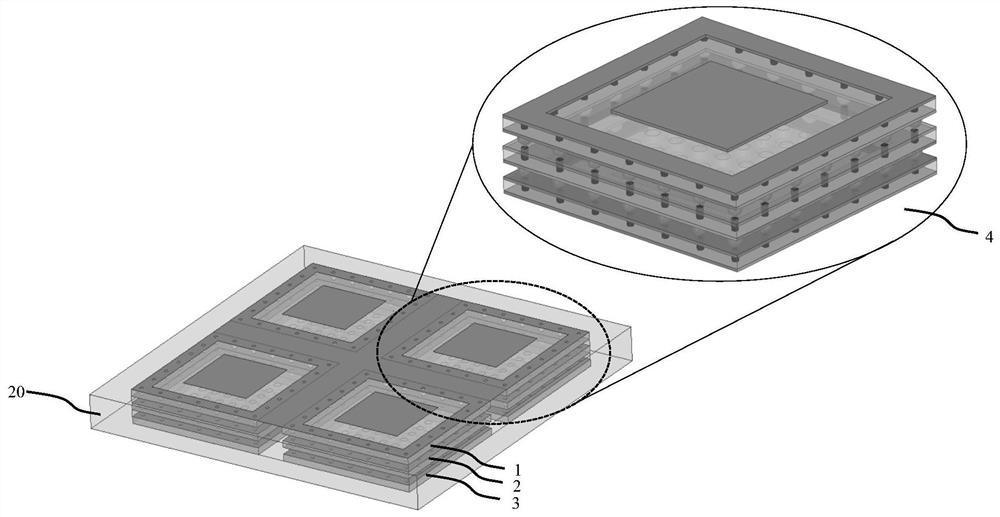
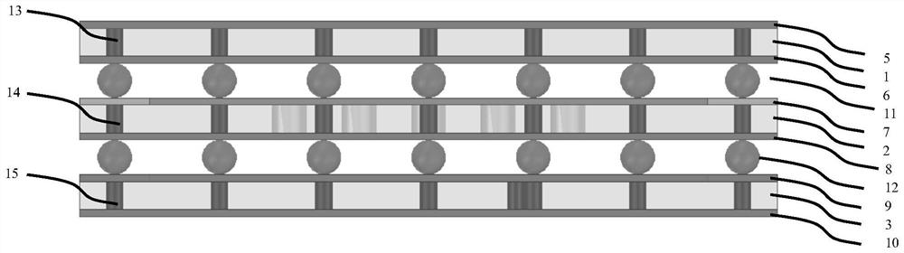
[0034] like Figures 1 to 8 As shown, a radio frequency microelectromechanical microstrip antenna includes a metal outer frame 20 and a rectangular array of microstrip antenna units 4 located inside the metal outer frame 20. The microstrip antenna unit 4 includes a first Adapter board 1, second adapter board 2 and third adapter board 3;

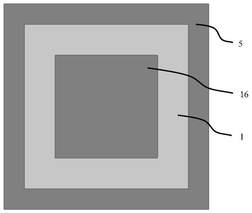
[0035] The first, second, and third adapter plates are all provided with metal shielding structures surrounding the central area of ​​the respective adapter plates. A metal shieldi...


PUM


Abstract

The invention discloses a radio frequency microelectromechanical microstrip antenna, which belongs to the technical field of wireless communication. It includes a metal outer frame and a microstrip antenna unit. The microstrip antenna unit includes a first adapter plate, a second adapter plate and a third adapter plate; the three adapter plates are provided with a central area surrounding the respective adapter plates. There is a metal shielding structure, and the vertical interconnection of the metal shielding structure is realized through the BGA interconnection structure between the three adapter plates; the front side of the first adapter plate is provided with a first radiation patch; the second adapter plate is provided with air holes and parasitic patches; the front side of the third adapter plate is provided with a second radiation patch, and the back side is provided with a reflective surface; a feed hole and a ground hole are arranged in the central area of ​​the third adapter plate. The invention has the characteristics of low profile, high gain and high bandwidth, and can solve the problems of narrow bandwidth and low gain of the low profile microstrip antenna of the high dielectric constant semiconductor substrate.

Description

technical field [0001] The invention relates to the technical field of wireless communication, in particular to a radio frequency microelectromechanical microstrip antenna. Background technique [0002] With the continuous development of communication technology, electromagnetic waves have gradually developed from the low frequency and high frequency range to the radio frequency and microwave range. Traditional antenna technologies, such as horn antennas, log-periodic antennas, Cassegrain antennas, Yagi antennas, and reflector antennas, have problems such as large volume, high profile height, and large installation structure. Compared with traditional antennas, strip antennas have the advantages of low profile, small volume, and easy integration. Therefore, microstrip antennas based on semiconductor substrates are increasingly used in satellite communications, mobile communications and other fields. [0003] A microstrip antenna based on a semiconductor substrate refers to ...

Claims


Application Information

Patent Timeline
Patent Type & Authority Patents(China)
IPC IPC(8): H01Q1/38H01Q1/52H01Q19/10H01Q21/06
CPCH01Q1/38H01Q1/526H01Q19/104H01Q21/065
Inventor 魏浩韩威贾世旺刘巍巍赵飞梁栋张苗苗
Owner NO 54 INST OF CHINA ELECTRONICS SCI & TECH GRP
Why Eureka
Try Eureka