Backlight source used for liquid crystal television

A technology of LCD TV and backlight, which is applied to color TV parts, TV system parts, TVs, etc. It can solve the problems of light guide plate distortion and poor LCD screen display, and achieve reduced thickness, uniform light, and Solve the effect of poor display screen

Inactive Publication Date: 2017-04-26
YANCHENG SANDING ELECTRONICS TECH CO LTD
View PDF0 Cites 5 Cited by
  • Summary
  • Abstract
  • Description
  • Claims
  • Application Information

AI Technical Summary

Problems solved by technology

[0004] The object of the present invention is to provide a backlight for LCD TV. The backlight is a side-in LED backlight. Its overall structure is ingeniously designed. On the other hand, it can also ensure that the backlight has a high degree of light uniformity and brightness

Method used


Image

  • Backlight source used for liquid crystal television
  • Backlight source used for liquid crystal television

Examples


Embodiment Construction

[0017] In order to deepen the understanding and recognition of the present invention, the present invention will be further described and introduced below in conjunction with the accompanying drawings.

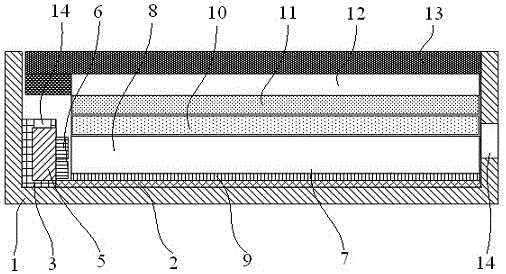
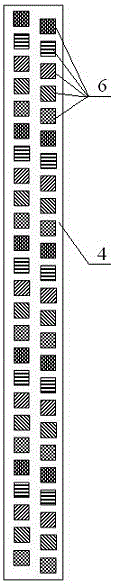
[0018] Such as figure 1 As shown, a backlight source for LCD TVs includes a light guide plate assembly 7, an LED light bar 4, a PMMA diffuser plate 10, a DBEF enhancement sheet 11, a black and white light-shielding double-sided plastic frame 12, a U-shaped inner plastic frame 2 and an outer The iron frame 1, the U-shaped inner plastic frame 2 is placed inside the outer iron frame 1, and is used for cushioning and protecting the optical components placed in the inner rubber frame 2, and can also effectively improve the positional stability of the optical components. The light guide plate assembly 7 , the PMMA diffuser plate 10 and the DBEF brightness enhancement sheet 11 are sequentially attached and placed in the U-shaped inner plastic frame 2 from bottom to top. On the inner...


PUM

PropertyMeasurementUnit
thicknessaaaaaaaaaa

Abstract

The invention relates to a backlight source used for a liquid crystal television. The backlight source comprises a light guide plate assembly, an LED lamp strip, a PMMA diffuser plate, a DBEF light enhancement sheet, a black-white shading double-faced adhesive tape frame, a U-shaped inner glue frame and an outer iron frame, wherein the inner glue frame is arranged inside the outer iron frame, an LED lamp strip clamping groove is arranged at one end, disposed at the inner glue frame, on the inner wall of the outer iron frame, the light guide plate assembly, the PMMA diffuser plate and DBEF light enhancement sheet are successively arranged in the inner glue frame in an attached mode from bottom to top, the LED lamp strip is placed in the LED lamp strip clamping groove, the black-white shading double-faced adhesive tape frame is adhered to the top portion of the DBEF light enhancement sheet, the LED lamp strip clamping groove is completely shielded, and a liquid crystal display screen is adhered to the upper portion of the black-white shading double-faced adhesive tape frame; and the light guide assembly comprises an optical glass light guide plate and a reflective film layer adhered to the bottom of the light guide plate, the LED lamp strip comprises an aluminum-base copper-clad laminate and a plurality of SMD LED lamp beads, the LED lamp beads are welded to the aluminum-base copper-clad laminate, the LED lamp beads and the aluminum-base copper-clad laminate are attached together by use of heat conduction silica gel, and the LED lamp beads are right opposite to the side incident surface of the optical glass light guide plate.

Description

technical field [0001] The invention relates to an LED backlight source for a liquid crystal television, in particular to a side-entry LED backlight source for an ultra-thin liquid crystal television. Background technique [0002] With the development and progress of LCD TV technology, LCD TVs are developing in the direction of thinness, beauty, fashion, low energy consumption, and low radiation. LED backlights have become LCD TVs because of their thinness, low energy consumption, and long service life. The mainstream of TV backlight. At present, the light input methods of LED backlight can be divided into direct light input and side light input. Among them, the direct light input is to place the LED light source at the bottom of the diffuser plate, so that the light is incident from the bottom, and the LED light source and the diffuser There is a certain incident distance between the plates, and the diffuser plate is used to diffuse the light into a surface. The side-inpu...

Claims


Application Information

Patent Timeline
Patent Type & Authority Applications(China)
IPC IPC(8): G02F1/13357G02B6/00H04N5/64
CPCG02F1/133615G02B6/0055G02B6/0065H04N5/64
Inventor 赵圣铭
Owner YANCHENG SANDING ELECTRONICS TECH CO LTD
Why Eureka
Try Eureka