Supercharge Your Innovation With Domain-Expert AI Agents!

Frame strander rotary air bag

A frame stranding machine and air bag technology, applied in the manufacture of electrical components, circuits, cables/conductors, etc., can solve the problems of poor sealing, short service life, complex heat dissipation structure, etc., and achieve good sealing, convenient processing and manufacturing, and location Set flexible effects

Inactive Publication Date: 2017-04-26
常州晨翔机械有限公司
View PDF5 Cites 0 Cited by
  • Summary
  • Abstract
  • Description
  • Claims
  • Application Information

AI Technical Summary

Problems solved by technology

[0009] The purpose of the present invention is to overcome the disadvantages of poor sealing, complex heat dissipation structure, and short service life of the existing rotary air bag, and provide a rotary air bag for a frame stranding machine. Using the technical solution of the present invention, the air bag on both sides of the air cavity of the sealing sleeve Sealed by the rotary seal ring, the rotary seal ring has an annular accommodation groove with a number of springs distributed along the circumferential direction of the rotary seal ring, so that the rotary seal ring is close to the seal sleeve and the shaft sleeve, which effectively compensates for material wear and parts fit The offset and eccentricity of the air cavity can be effectively sealed, and under the action of compressed air, the inner and outer walls of the annular accommodation groove of the rotary sealing ring can be more closely contacted with the sealing sleeve and the shaft sleeve, and the sealing performance is better; at the same time, using The inner bearing sleeve, sealing sleeve and outer bearing sleeve made of aluminum alloy greatly improve the heat dissipation efficiency of the rotating air bag, no additional cooling mechanism is required, the structure is simpler, the production and assembly are more convenient, and the service life is longer

Method used


Image

  • Frame strander rotary air bag
  • Frame strander rotary air bag
  • Frame strander rotary air bag

Examples


Embodiment

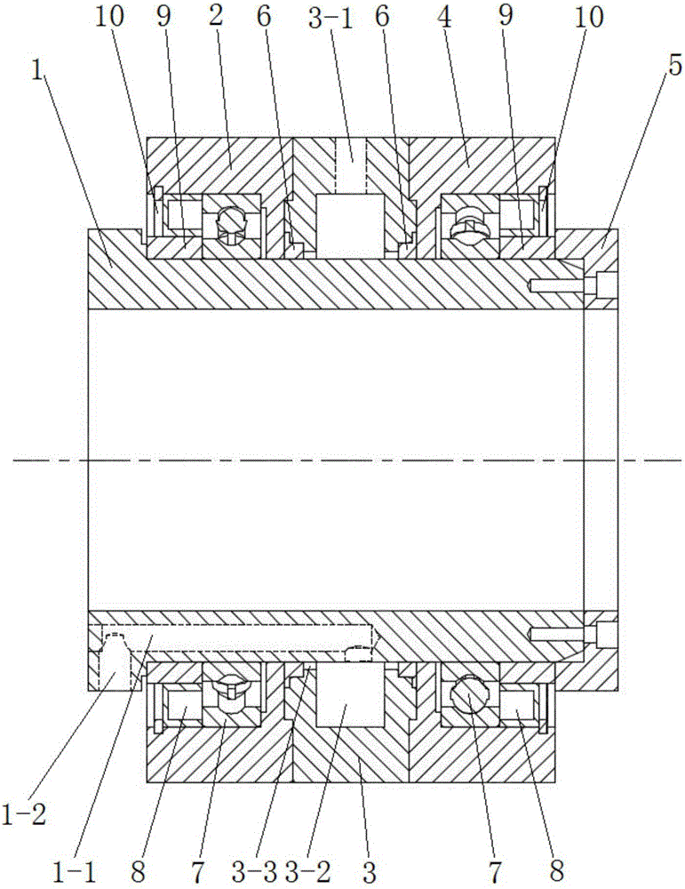
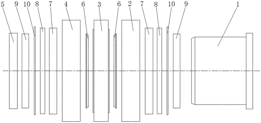
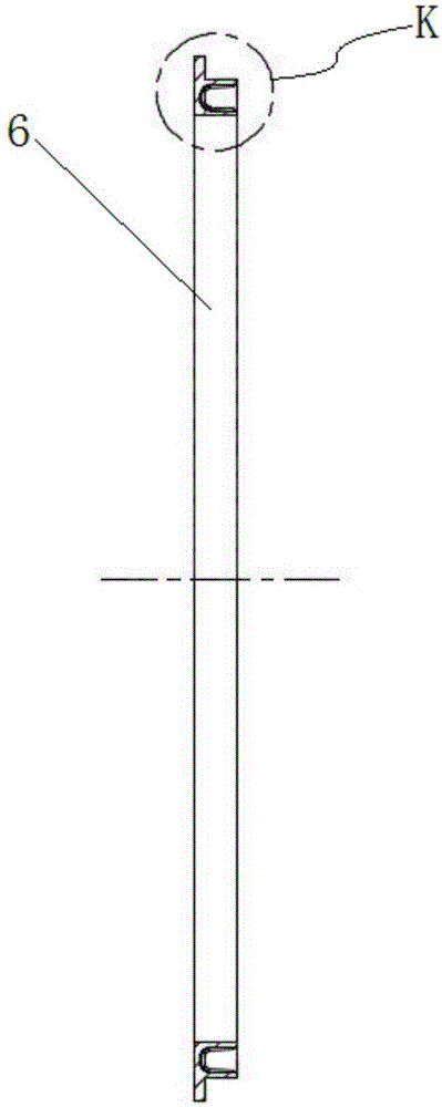
[0039] combine Figure 1 to Figure 4As shown, a rotating air bag of a frame stranding machine in this embodiment includes a shaft sleeve 1, an inner bearing sleeve 2, a sealing sleeve 3, an outer bearing sleeve 4 and a fixed sleeve 5 installed at the end of the shaft sleeve 1, and the shaft sleeve 1 One end has a shoulder structure, the inner bearing sleeve 2, the sealing sleeve 3 and the outer bearing sleeve 4 are sleeved on the shaft sleeve 1 in turn, and the inner bearing sleeve 2, the sealing sleeve 3 and the outer bearing sleeve 4 are fixedly connected, preferably Ground, the inner bearing sleeve 2, the sealing sleeve 3 and the outer bearing sleeve 4 are fixedly connected by bolts, which is convenient for disassembly and maintenance; There is a bearing assembly, an air chamber 3-2 and sealing grooves located on both sides of the air chamber 3-2 are arranged between the sealing sleeve 3 and the shaft sleeve 1, and a rotating sealing ring 6 is installed in the sealing groov...


PUM

PropertyMeasurementUnit
Surface roughnessaaaaaaaaaa
Surface hardnessaaaaaaaaaa

Abstract

The invention discloses a frame strander rotary air bag, belonging to the field of conductive cable stranding machines. The frame strander rotary air bag comprises a shaft sleeve, an inner bearing sleeve, a sealing sleeve, an outer bearing sleeve and a fixing sleeve. The inner bearing sleeve, the sealing sleeve, and the outer bearing sleeve orderly sleeve the shaft sleeve. The inner bearing sleeve and the outer bearing sleeve are provided with bearing components. An air cavity and a sealing groove at two sides of the air cavity are arranged between the sealing sleeve and the shaft sleeve. A rotating sealing ring is installed in the sealing groove. One side of the rotating sealing ring is provided with an annular containing groove. A plurality of springs which press the inner and outer walls of the annular containing groove are distributed along the circumferential direction of the rotating sealing ring in the annular containing groove. The annular containing groove communicates with the air cavity through a ring groove arranged between the sealing sleeve and the shaft sleeve. According to the frame strander rotary air bag, the material wear and offset and eccentricity of component fit are made up, thus the air cavity is effectively sealed, under the effect of compressed air, the rotating sealing ring can be more closely in contact with the sealing ring and the shaft sleeve, the sealing performance is good, and a cooling mechanism is not needed at the same time.

Description

technical field [0001] The invention relates to a compressed air rotary air intake device, in particular to a rotary air bag for a frame winch. Background technique [0002] In the wire and cable industry, stranding is the basic process for the production of overhead wires and conductive cores of power cables, and the frame stranding machine (also known as cage stranding machine or tube stranding machine or cable forming machine) is one of the main stranding equipment . The existing frame stranding machine adopts pneumatic control, the compressed air is introduced into the winch cage through the rotating air bag (also known as the rotating air inlet), and a set of pneumatic tension device is installed on the fixed thimble of each pay-off reel. Or install a set of tension control levers in each row in the winch cage, which can adjust the pressure of compressed air according to the wire diameter of the pay-off reel, so that the single-wire pay-off tension remains uniform, and...

Claims


Application Information

Patent Timeline
IPC IPC(8): H01B13/02
CPCH01B13/0207
Inventor 江翔江晨
Owner 常州晨翔机械有限公司
Features
  • R&D
  • Intellectual Property
  • Life Sciences
  • Materials
  • Tech Scout
  • Unparalleled Data Quality
  • Higher Quality Content
  • 60% Fewer Hallucinations
Learn More