Energy collection utilization system and method thereof

A technology of energy collection and electric energy, which is applied in current collectors, transportation and packaging, electric vehicles, etc., can solve the problems of unstable collected energy, achieve the effects of reducing the number of charge and discharge, simple system, and broad application prospects

Pending Publication Date: 2017-04-26
安荣邦
View PDF5 Cites 17 Cited by
  • Summary
  • Abstract
  • Description
  • Claims
  • Application Information

AI Technical Summary

Problems solved by technology

[0004] However, one of the main challenges of energy harvesting is that usually the energy that is harvested is so small that the energy consumed by the harvesting system itself may be greater than the energy harvested
Another major challenge is that the energy being harvested is not stable

Method used


Image

  • Energy collection utilization system and method thereof
  • Energy collection utilization system and method thereof
  • Energy collection utilization system and method thereof

Examples


Embodiment 1

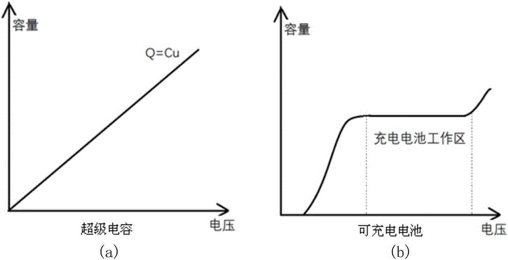
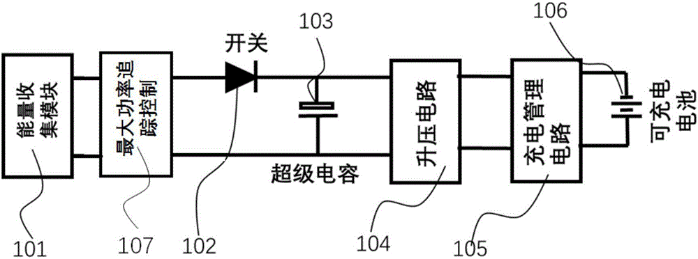
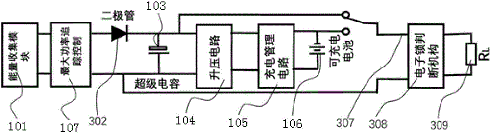
[0050] Figure 4 It is a realization diagram of the present invention applied to an electronic door lock. In the figure, the solar panel 501 converts light energy into electrical energy; the function of the module 107 is to track the maximum power output point of the solar panel and keep working on this output point; directly store the electrical energy in the supercapacitor 103 through the diode 302, The advantage of this structure is that as long as the solar panel 501 outputs a lot of electric energy, the electric energy can be stored in the supercapacitor 103; since the internal resistance of the supercapacitor 103 is very small, the supercapacitor 103 will Far superior to rechargeable batteries 106. When the energy accumulated on the supercapacitor 103 reaches a certain level, the boost circuit 104 and the charging management circuit 105 are turned on. Charging of the rechargeable battery 106 is started. The reason why electric energy is moved to rechargeable battery 1...

Embodiment 2

[0059] Figure 5 is a block diagram of an energy harvesting sensor implementation for a parking space occupancy sensor.

[0060] With the improvement of people's living standards, the number of family cars is increasing rapidly. Then came the parking problem. Sometimes we can't find a suitable parking space in a parking lot for a long time, and forget the location of the car when we come back after parking the car. If we can realize the intelligentization of parking space and car search, then this problem will Easy to solve. The basis of establishing a smart parking lot is the sensor. We know that the sensor needs electricity, and laying wires and using batteries do not seem to be a good solution. It is a good solution to use the pressure of the car when it is parked to solve the power of the sensor. Figure 5 is a block diagram of how to solve this problem.

[0061] The function of the pressure energy collection plate 601 is to convert the pressure into electric energy. T...


PUM


Abstract

The invention relates to the electric energy storage and utilization technology field and provides an energy collection utilization system and a method thereof. The system comprises an energy collection module, a maximum power tracking control circuit, a super capacitor, a boosted circuit, a charging management circuit and a rechargeable battery. The energy collection module is used for collecting energy and converting the collected energy into electric energy. The electric energy is unidirectionally transmitted to and stored to the super capacitor through the maximum power tracking control circuit. The super capacitor is connected to the rechargeable battery through the boosted circuit and the charging management circuit. When an electric quantity stored in the capacitor is greater than a setting threshold, the super capacitor charges the rechargeable battery. The system and the method have advantages that the system takes the super capacitor as power supply energy most of the time so that charge and discharge frequencies of the rechargeable battery are reduced and a service life of the system is greatly prolonged; the system acquires energy from a surrounding environment during a whole life cycle and is always maintained to be in a work state so that the system becomes a real maintenance-free system; and the system is simple and practical, and an application prospect is wide.

Description

technical field [0001] The invention relates to the technical field of electric energy storage and utilization, in particular to an energy collection and utilization system and method. Background technique [0002] In today's era, we are entering an environment that relies on sensors and big data to operate; at the bottom of this environment, there are countless sensors and execution devices; these sensors and execution devices have been relying on electricity for a long time In this way, it will face a very big challenge: how to supply power to so many sensors and execution devices; it is unrealistic to use power lines to supply power to so many sensors and execution devices. If it is powered by batteries, it requires huge human resources to maintain. At the same time, it will cause great pollution to the environment. In 2015, the number of batteries produced in China was 14 billion. And the number of batteries consumed by our country itself has reached half of the produ...

Claims


Application Information

Patent Timeline
Patent Type & Authority Applications(China)
IPC IPC(8): H02J7/34H02J7/35H02J7/32
CPCH02J7/32H02J7/34H02J7/345H02J7/35Y02E10/56
Inventor 安荣邦
Owner 安荣邦
Why Eureka
Try Eureka