Efficient permanent magnetism kinetic energy (wheel) self-loop generator set

A generator set and self-circulation technology, applied to electrical components, electromechanical devices, etc., can solve problems such as high requirements, immaturity, and insufficient driving force, and achieve the effect of high efficiency, perfect structure, and reasonable appearance

Inactive Publication Date: 2017-04-26
朱万君
View PDF0 Cites 5 Cited by
  • Summary
  • Abstract
  • Description
  • Claims
  • Application Information

AI Technical Summary

Problems solved by technology

[0002] At present, most of the known generating sets are driven by wind power, fire power, hydraulic power, diesel oil, etc., and are connected to the support of the generating set or through the transmission mode of a gear box to realize power generation. High investment costs, long construction period, and high environmental requirements, such as hydroelectric power stations, seriously restrict the rapid development of the electric power industry. Nowadays, researchers from all over the world pay more attention to the high power and high precision control of these generators to improve power generation. Technological development and innovation in terms of efficiency, etc., but innovation in driving force is not enough. Although there are technologies to realize magnetic power or generator sets through magnetic kinetic energy, the above-mentioned technologies are not mature enough. The main defect lies in how to change the power. Good automatic distribution, and low power compensation performance; secondly, the structural design of the entire generator set in the existing technology is unreasonable, resulting in insufficient performance of its magnetic kinetic energy

Method used


Image

  • Efficient permanent magnetism kinetic energy (wheel) self-loop generator set
  • Efficient permanent magnetism kinetic energy (wheel) self-loop generator set
  • Efficient permanent magnetism kinetic energy (wheel) self-loop generator set

Examples


Embodiment Construction

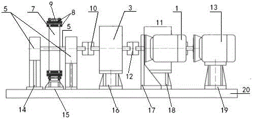
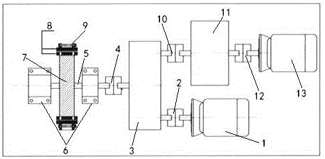
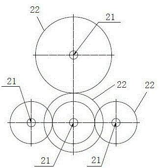
[0025] In order to enable those skilled in the art to better understand the technical solution of the present invention, the technical solution of the present invention will be further described below in conjunction with the accompanying drawings and embodiments.

[0026] Refer to attached Figure 1-5 The high-efficiency permanent magnet kinetic energy (wheel) self-circulating generator set shown includes a starter motor 1, a power distribution box 3, a high-strength permanent magnet 8 power rotating device, and a generator 13. The starter motor 1 is connected to the The power distribution box 3 is connected, and the power distribution box 3 is connected with the high-strength permanent magnet 8 power rotating device through a coupling two 4, and the generator 13 is connected with a reduction box 11 through a coupling three 12, and the deceleration The box 11 is connected with the power distribution box 3 through a coupling four 10; the reduction box 11 is arranged on the redu...


PUM


Abstract

The present invention discloses an efficient permanent magnetism kinetic energy (wheel) self-loop generator set. The generator set comprises a starter motor, a power distribution box, a high-strength permanent magnet power rotation device and a generator. The starter motor is connected with the power distribution box through a coupler 1, the power distribution box is connected with the high-strength permanent magnet power rotation device through a coupler 2, the generator is connected with a reduction gearbox through a coupler 3, and the reduction gearbox is connected with the power distribution box through a coupler 4. The efficient permanent magnetism kinetic energy (wheel) self-loop generator set adds the power distribution box to allow the whole structure to be more reasonable, improved and practical and prompt the magnetic kinetic energy to perform larger efficiency.

Description

technical field [0001] The invention relates to a high-efficiency permanent magnet kinetic energy (wheel) self-circulation generator set. Background technique [0002] At present, most of the known generating sets are driven by wind power, fire power, hydraulic power, diesel oil, etc., and are connected to the support of the generating set or through the transmission mode of a gear box to realize power generation. High investment costs, long construction period, and high environmental requirements, such as hydroelectric power stations, seriously restrict the rapid development of the electric power industry. Nowadays, researchers from all over the world pay more attention to the high power and high precision control of these generators to improve power generation. Technological development and innovation in terms of efficiency, etc., but innovation in driving force is not enough. Although there are technologies to realize magnetic power or generator sets through magnetic kine...

Claims


Application Information

Patent Timeline
Patent Type & Authority Applications(China)
IPC IPC(8): H02K53/00
CPCH02K53/00
Inventor 朱万君
Owner 朱万君
Why Eureka
Try Eureka